Electric power steering apparatus

a technology of electric steering and electric motor, which is applied in the direction of electrical steering, association with control/drive circuit, transportation and packaging, etc., can solve the problems of high failure rate and parts of semiconductors

Inactive Publication Date: 2011-03-22
MITSUBISHI ELECTRIC CORP
View PDF12 Cites 15 Cited by
  • Summary
  • Abstract
  • Description
  • Claims
  • Application Information

AI Technical Summary

Benefits of technology

[0009]Accordingly, the present invention is intended to obviate the problems as referred to above, and has for its object to provide an electric power steering apparatus in which upon replacement of a drive control unit, it becomes possible to replace only the drive control unit with a new one without detaching the electric power steering apparatus from a gear housing, thereby improving the replacement operation of the drive control unit to a substantial extent.
[0011]According to the electric power steering apparatus of the present invention, the location of connection at which the connecting portion of the electric motor and the connecting portion of the drive control unit are electrically connected to each other is arranged at a joint location at which the end portions of the motor housing and the drive housing are joined to each other, so it becomes possible to detach the drive control unit alone without removing the electric motor from the gear housing after the electric power steering apparatus has been mounted on the gear housing, as a result of which the efficiency of the repair and replacement operation for the drive control unit can be improved.

Problems solved by technology

In the replacement of an electric power steering apparatus, only the drive control unit built therein, which includes a lot of semiconductor parts and has a high failure rate, is sometimes desired to be replaced.
That is, it is necessary to take the trouble of once detaching or dismounting the electric power steering apparatus from the gear housing of the power steering mechanism, then removing the screws in the electrically connecting portions through an opening portion of the motor housing at a gear housing side, thereafter detaching the drive control unit from the electric motor, and replacing it with a new one.

Method used


Image

  • Electric power steering apparatus
  • Electric power steering apparatus
  • Electric power steering apparatus

Examples


embodiment 1

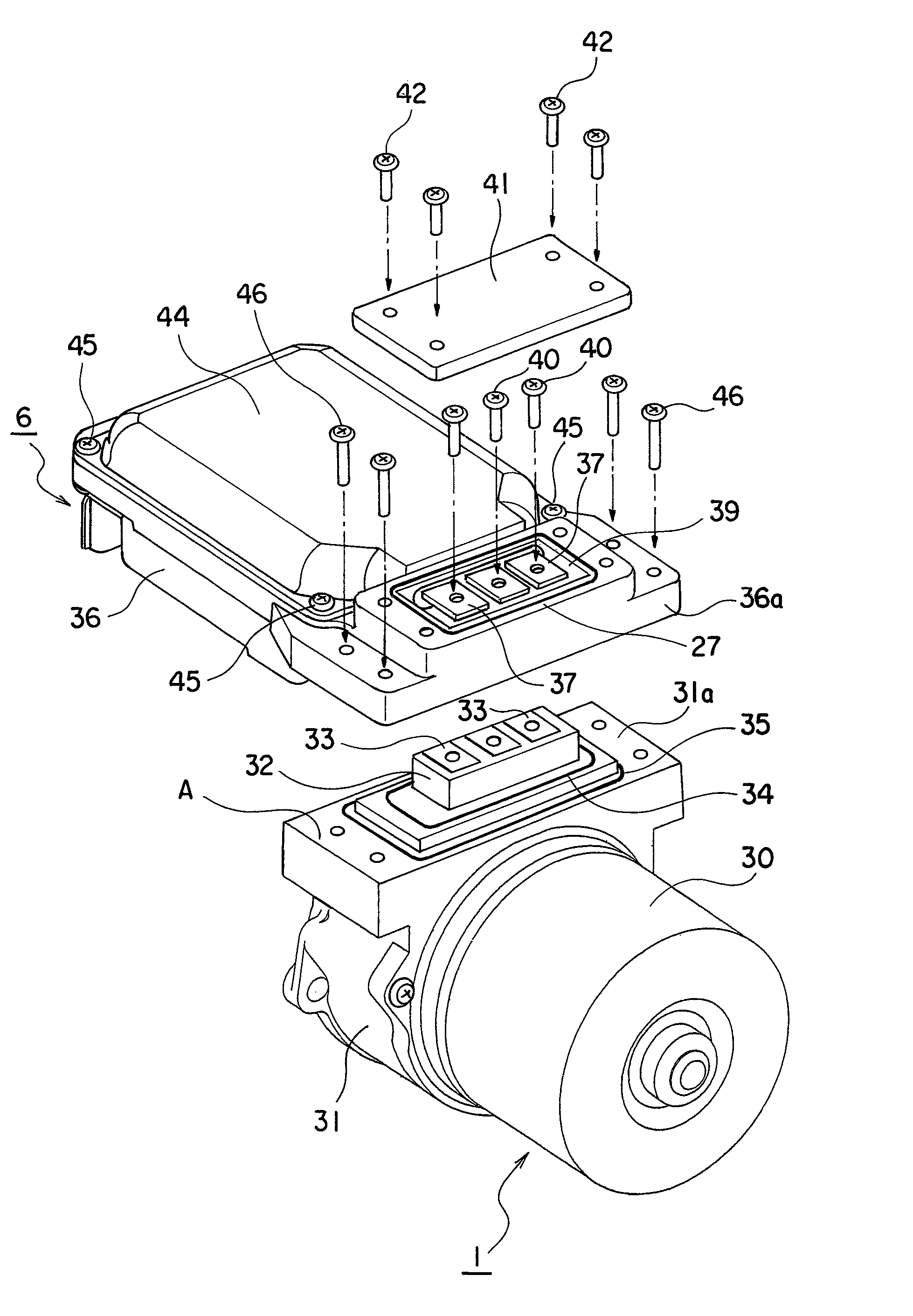
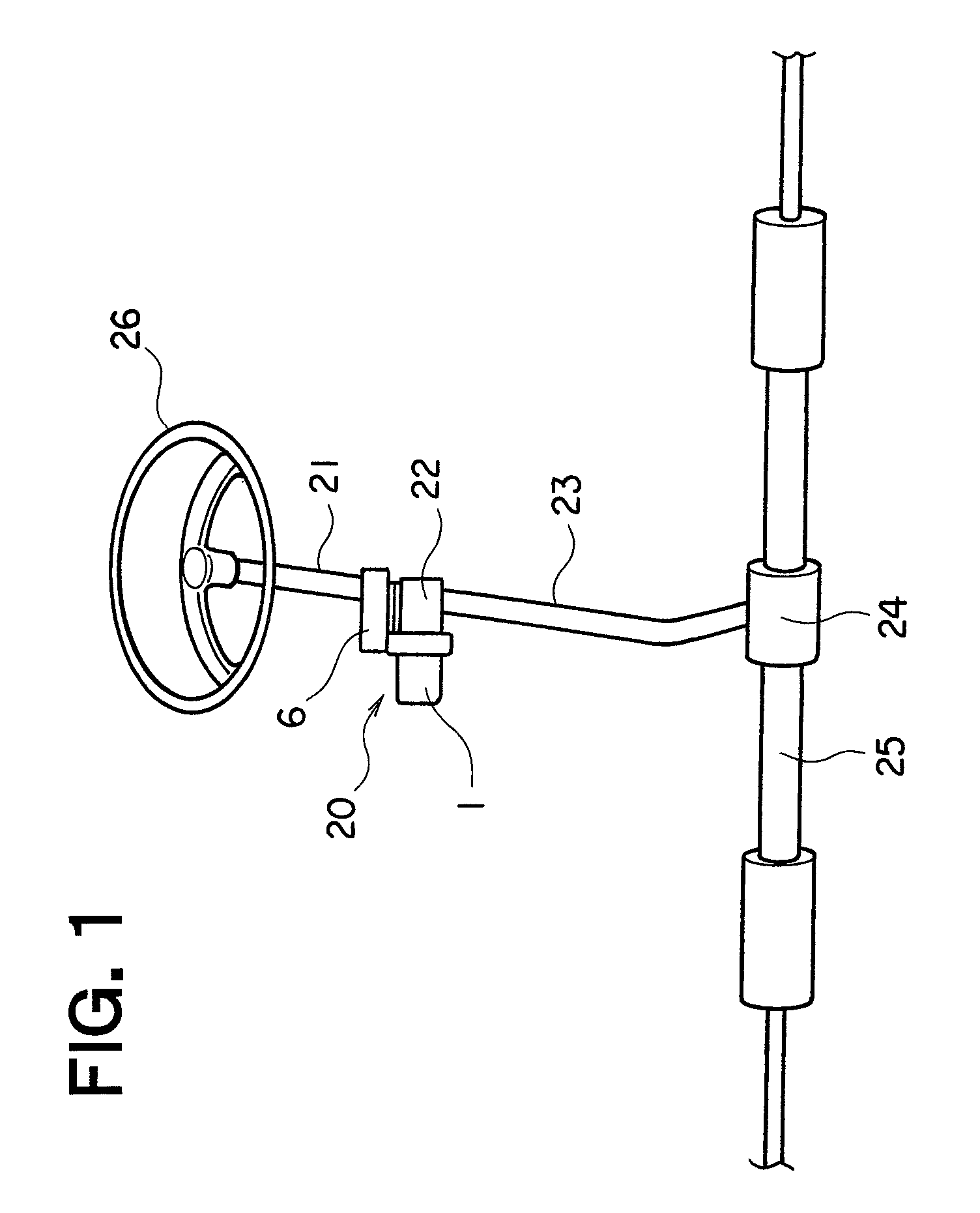
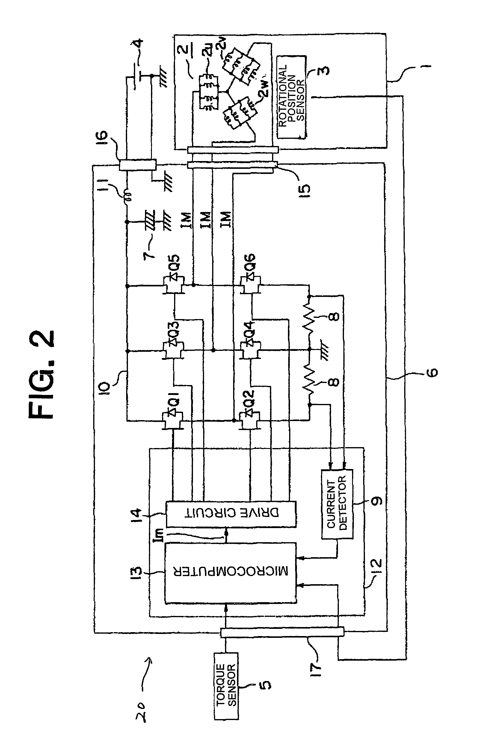
[0023]Referring to the drawings and first to FIG. 1, there is shown, in a perspective view, a power steering mechanism in which an electric power steering apparatus 20 according to a first embodiment of the present invention is incorporated. FIG. 2 is a block diagram of the electric power steering apparatus 20 in FIG. 1. FIG. 3 is a perspective view that shows the electric power steering apparatus 20 in FIG. 1. FIG. 4 is an exploded perspective view that shows the electric power steering apparatus 20 in FIG. 1.

[0024]In the power steering mechanism, a steering force from a steering wheel 26 of a vehicle is transmitted to a steering wheel joint 23 through a column shaft 21. The electric power steering apparatus 20 is mounted on the column shaft 21 through a gear housing 22 that receives therein a worm gear. The output (i.e., torque and the number of revolutions per minute) of an output shaft of an electric motor 1 of the electric power steering apparatus 20 is transmitted to a steerin...

embodiment 2

[0056]FIG. 5 is a perspective view that shows an electric power steering apparatus 20 according to a second embodiment of the present invention.

[0057]In this second embodiment of the present invention, a power supply terminal block 47 and power supply input bus bars 49, which serve as a connecting portion, are all arranged in a drive housing 36. The power supply input bus bars 49 extend from a motor housing 31 in diametrical directions

[0058]The power supply input bus bars 49 are in surface to surface contact with terminals of the power supply terminal block 47, and by fastening three screws 40 in an axial direction, the power supply input bus bars 49 are joined to the terminals of the power supply terminal block 47.

[0059]A drive housing 36 has an opening portion which is adapted to be closed with a cover 44 by using six screws 45. In addition, an O ring (not shown) is arranged between the drive housing 36 and the cover 44 for ensuring air tightness therebetween.

[0060]The constructio...

embodiment 3

[0064]FIG. 6 is a perspective view that shows an electric power steering apparatus according to a third embodiment of the present invention.

[0065]This third embodiment of the present invention is different from the above-mentioned first embodiment in that a drive control unit 6 is arranged at a side at which it overlaps with an electric motor 1 when seen along a direction perpendicular to the axis thereof.

[0066]The other construction of this third embodiment is similar to that of the first embodiment.

[0067]In this third embodiment of the present invention, it is preferable that in case where there is no space available in the diametrical surroundings of a gear housing 22, the drive control unit 6 can be arranged at a location not conflicting with the gear housing 22.

[0068]The effects of this third embodiment other than the above are similar to those of the first embodiment.


PUM


Abstract

A drive control unit alone can be replaced without detaching an electric power steering apparatus from a gear housing. A motor housing of an electric motor, which outputs assist torque to a steering wheel of a vehicle, and a drive housing of the drive control unit, which controls the driving of the electric motor, are coupled to each other at a mating surface in a surface to surface contact manner, and the drive housing and the gear housing are coupled with each other on the same axis. A location of connection, at which a power supply input terminal block of the electric motor and power supply bus bars of the drive control unit are connected to each other by us of screws, is arranged at a joint location at which the motor housing and the drive housing are joined to each other by screws.

Description

BACKGROUND OF THE INVENTION[0001]1. Field of the Invention[0002]The present invention relates to an electric power steering apparatus equipped with an electric motor for outputting assist torque to a steering wheel of a vehicle, and a drive control unit for controlling the driving of an output shaft of the electric motor.[0003]2. Description of the Related Art[0004]In the past, there has been known an electric power steering apparatus in which a motor housing of an electric motor, which is adapted to output an assist torque to a steering wheel of a vehicle, and a drive housing of a drive control unit, which serves to control the driving of an output shaft of the electric motor, are fixedly secured to each other at a mating surface in a surface to surface contact manner, and in which the motor housing and a gear housing that receives therein a gear connected with the output shaft of the electric motor are coupled with each other on the one and same axis (see, for example, a first pat...

Claims


Application Information

Patent Timeline
Patent Type & Authority Patents(United States)
IPC IPC(8): B62D5/04
CPCB62D5/0406H02K11/0073H02K5/225H02K11/33
Inventor MORIKAWA, AKIHIKOASAO, YOSHIHITOFUJIMOTO, TADAYUKI
Owner MITSUBISHI ELECTRIC CORP
Why Eureka
Try Eureka