Embedded thin films

a technology of embedded thin films and thin films, which is applied in the direction of printed resistor incorporation, coating, printed capacitor incorporation, etc., can solve the problems of energy inefficiency, metal embrittlement and/or separation of conductors from substrates, and suboptimal properties of resulting devices, so as to reduce the hydrolysis generation of hydrogen and avoid corrosive conditions

Inactive Publication Date: 2014-11-11
THE RES FOUND OF STATE UNIV OF NEW YORK
View PDF14 Cites 1 Cited by
  • Summary
  • Abstract
  • Description
  • Claims
  • Application Information

AI Technical Summary

Benefits of technology

[0013]The present systems and methods provide an electrochemical process for coating a conductive surface with a ceramic or insoluble or low solubility metal salt. This coating may be porous, and therefore formed with a range of thickness. The process reduces hydrolytic generation of hydrogen while avoiding corrosive conditions at the cathode.
[0014]According to one embodiment, ceramic thin films of high capacitance (i.e., high dielectric strength) materials are embedded within the inner layers of electronic packages or circuit boards and replace the need for placement and assembly operations of discrete surface mounted components. The ceramic films have the following advantages over existing ceramic-filled epoxy or ceramic paste dielectrics or conductors:

Problems solved by technology
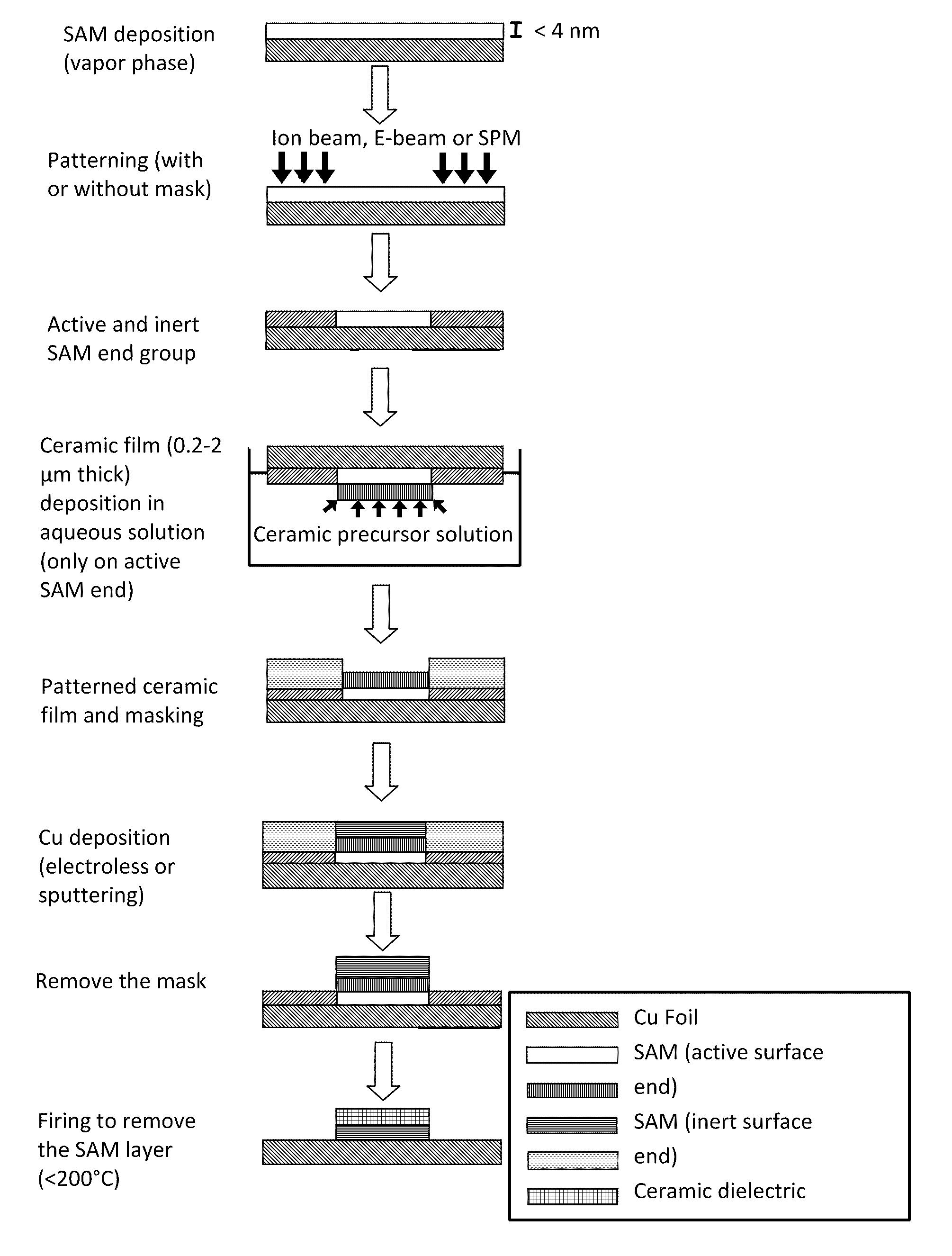
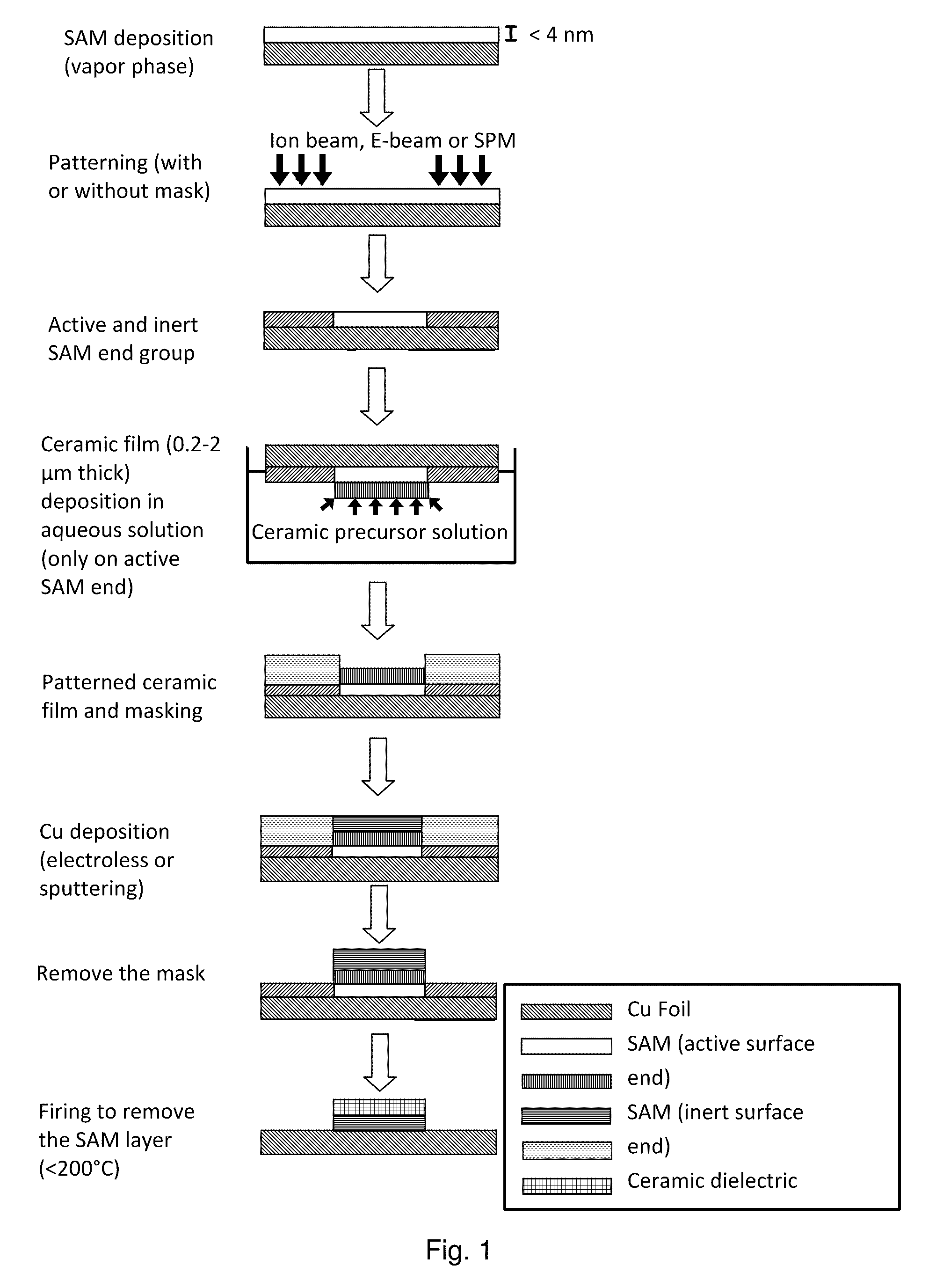
The electrochemical process, however, is associated with a corrosive and hostile environment to the underlying conductor, e.g., copper, leading to suboptimal properties of the resulting device.
In particular, the environment during the deposition or a post-deposition conversion process may be oxidizing, resulting in corrosion of the copper or other metal and reaction with solutes, and hydrolysis of the aqueous solvent and generation of hydrogen, resulting in embrittlement of the metal and / or separation of the conductor from its substrate.
The hydrolysis also results in energy inefficiency.
In some cases, an electrochemical process leads to a protective coating which is non-conductive, and is thus self-limiting with respect to the conduct of an electrochemical process through the coating.
Therefore, such processes are typically limited to thin protecting coatings (e.g., an anodization process to produce a protective oxide).
Formation of coatings of arbitrary thickness is difficult, and the coatings may have properties which are limited by the process conditions, and not as an independently controlled factor over a range of thicknesses.
Therefore, the electrochemical formation of coatings on conductive surfaces are disfavored as compared to deposited thick films for the fabrication of embedded devices.

Method used


Image

  • Embedded thin films
  • Embedded thin films
  • Embedded thin films

Examples


example 2

[0078]A ceramic film was deposited under the following conditions:

[0079]Solution: Methanol:Water=1:1 v / v, TiCl4=0.02 M, H2O2=0.2

[0080]Voltage: 10V, Electrode distance 2 cm, CD=100 mA / cm2, Time 120 s

[0081]The process produced a 2000-nm thick film, which is shown in the photomicrographs of FIGS. 4A, 4B, and 4C at varying increasing magnifications.

example 3

[0082]A deposition of titania films on commercial copper / FR4 / copper laminates was conducted under the following conditions:

[0083]Solution: Methanol:Water=95:5 v / v, TiCl4=0.02 M, H2O2=0.1 M

[0084]Voltage: 10V, Electrode distance 2 cm, CD=100 mA / cm2, Time 20 / 20 / 20 s (three 20 second intervals). Multiple deposition periods were adopted to reduce through-the-layer cracks. Electron micrographs of the resultant films are shown in FIGS. 5A and 5B, at varying magnification.

example 4

[0085]A deposition was conducted of titania films on 500 nm thick copper sputtered on a polyimide (PI) surface under the following conditions:

[0086]Solution: Methanol:Water=95:5 v / v, TiCl4=0.02 M. (without H2O2 in the electrolyte.)

[0087]Voltage: 10V, Electrode distance 2 cm, CD=15 mA / cm2, Time 120 s

[0088]The process, which did not use hydrogen peroxide, produces a very porous structure, with evident cracking at lower magnifications, as shown in FIGS. 6A, 6B and 6C.


PUM

PropertyMeasurementUnit
cathodic voltage potentialaaaaaaaaaa
thicknessaaaaaaaaaa

Abstract

A method for forming a film on a conductive substrate, comprising immersing a substrate having a conductive portion in a solution comprising a metal ion ceramic precursor for the film and a peroxide; applying a voltage potential to the conductive portion with respect to a counter electrode in the solution, sufficient to protect the conductive portion from corrosion by the solution, and drive formation of a film on the substrate, controlling a pH of the solution while limiting a production of hydrogen by electrolysis of the solution proximate to the conductive portion; and maintaining the voltage potential for a sufficient duration to produce a film on the conductive portion. An electrode may be formed over the film to produce an electrical device. The film may be, for example, insulating, dielectric, resistive, semiconductive, magnetic, or ferromagnetic.

Description

BACKGROUND OF THE INVENTION[0001]1. Field of the Invention[0002]The present invention relates, in general, to systems and methods for forming thin film structures on conductive surfaces, for example, printed circuit boards (PCBs), microelectromechanical (MEM) devices, sensors, and other structures.[0003]2. Description of the Prior Art[0004]As electronic circuit boards become crowded with numerous discrete components, additional advances will require utilization of the inner spaces of electronics packaging for embedded component placement. The embedding of the passive components inside packaging, circuit boards, and interconnections is starting to emerge in the industry as the process effectively combines manufacturing, component packaging and component assembly into a single manufacturing process flow. This embedded technology can thus achieve size reduction, increased functionality, improved high frequency performance, cost savings and increased reliability.[0005]Typically, discret...

Claims


Application Information

Patent Timeline
Patent Type & Authority Patents(United States)
IPC IPC(8): H05K1/16H05K3/18C25D9/08C25D5/48
CPCC25D5/48H05K2203/135H05K2201/0355C25D9/08H05K2201/0175H05K3/184H05K1/162H05K2203/092C25D21/12H05K1/0306H05K1/09H05K1/167H05K3/0011H05K2203/163
Inventor CHO, JUNGHYUNSAMMAKIA, BAHGATPOLIKS, MARK D.MAGNUSON, ROYROY, BIPLAB KUMAR
Owner THE RES FOUND OF STATE UNIV OF NEW YORK
Why Eureka
Try Eureka