Projector unit and projection television apparatus

a technology of projection television and projector unit, which is applied in the direction of lighting and heating apparatus, television systems, instruments, etc., can solve the problems of cumbersome replacement operation, deterioration of high labor intensity, so as to improve convenience of use and maintain advantageous image quality on the screen

Inactive Publication Date: 2007-01-25
SONY CORP
View PDF8 Cites 1 Cited by
  • Summary
  • Abstract
  • Description
  • Claims
  • Application Information

AI Technical Summary

Benefits of technology

[0017] Accordingly, replacement of the light source section can be performed simply, and this is advantageous in enhancement of the convenience in use of the projector unit and the projection television apparatus.
[0018] Further, since the locked state wherein the mating por

Problems solved by technology

Therefore, the replacing operation is cumbersome and takes much time and labor.
However, if the screws are somewhat loose, then the optical axis of the light source section and the opti

Method used


Image

  • Projector unit and projection television apparatus
  • Projector unit and projection television apparatus
  • Projector unit and projection television apparatus

Examples


Embodiment Construction

[0037] In the following, a projector unit and a projection television apparatus to which an embodiment of the present invention is applied are described in detail with reference to the accompanying drawings.

[0038] First, a configuration of the projection television apparatus is described.

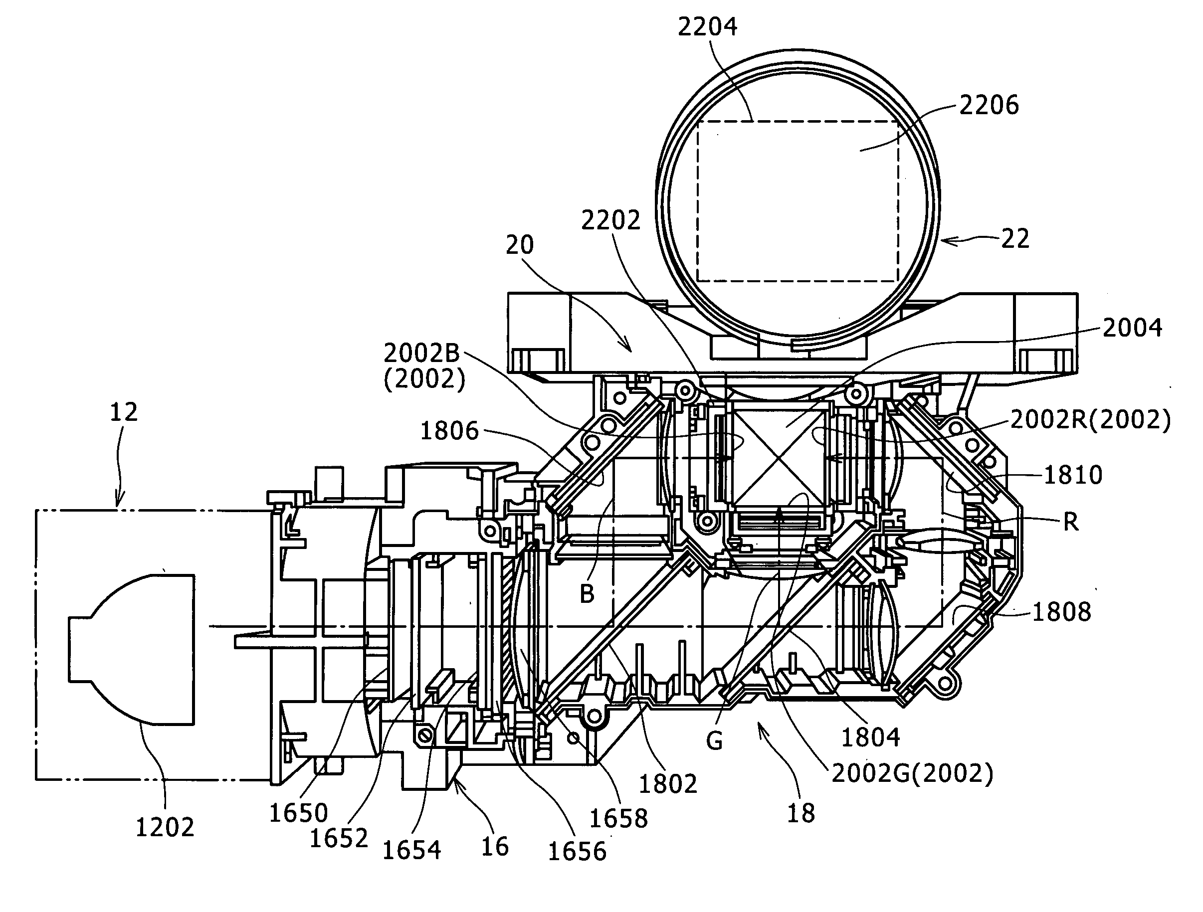
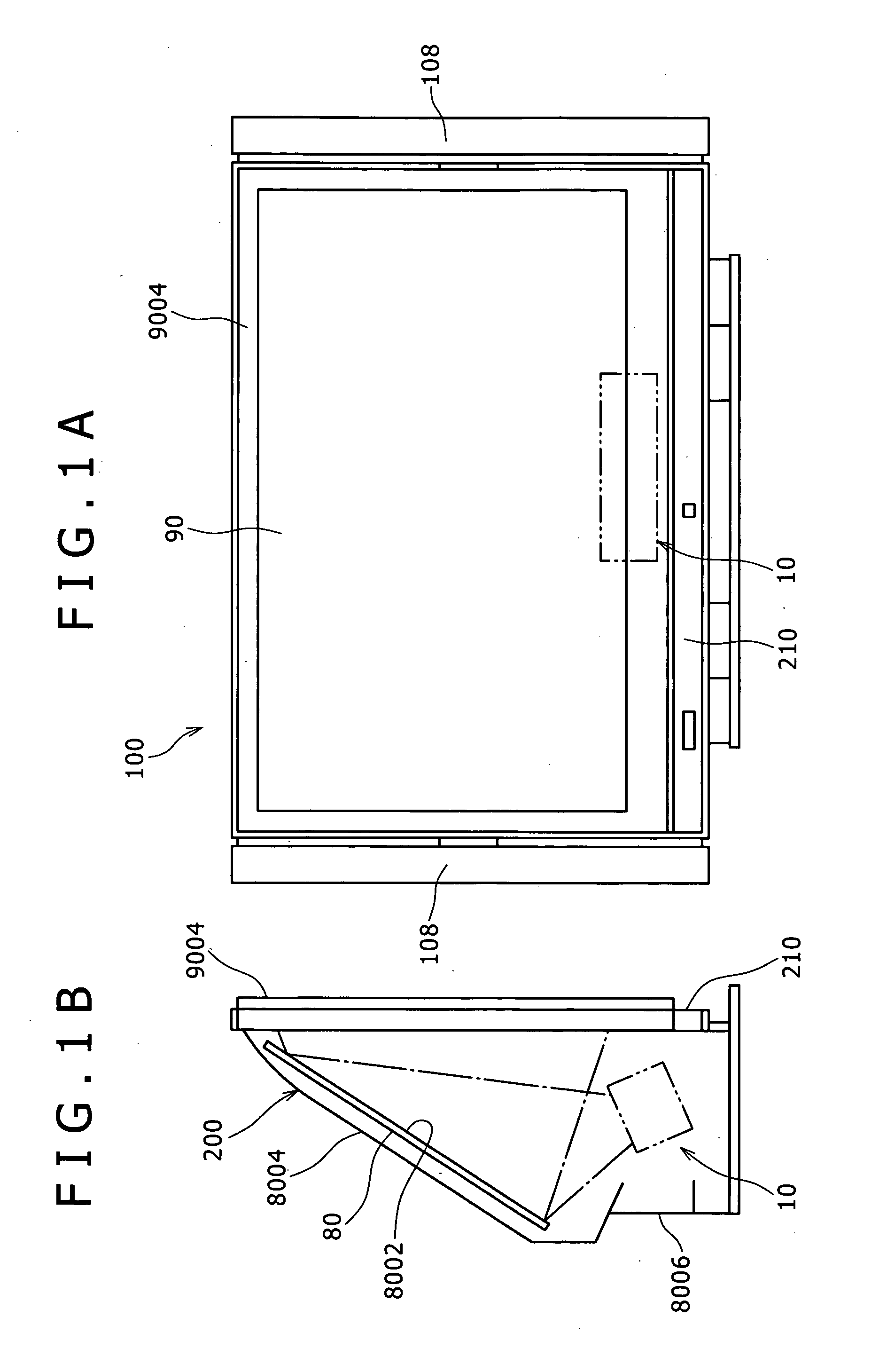
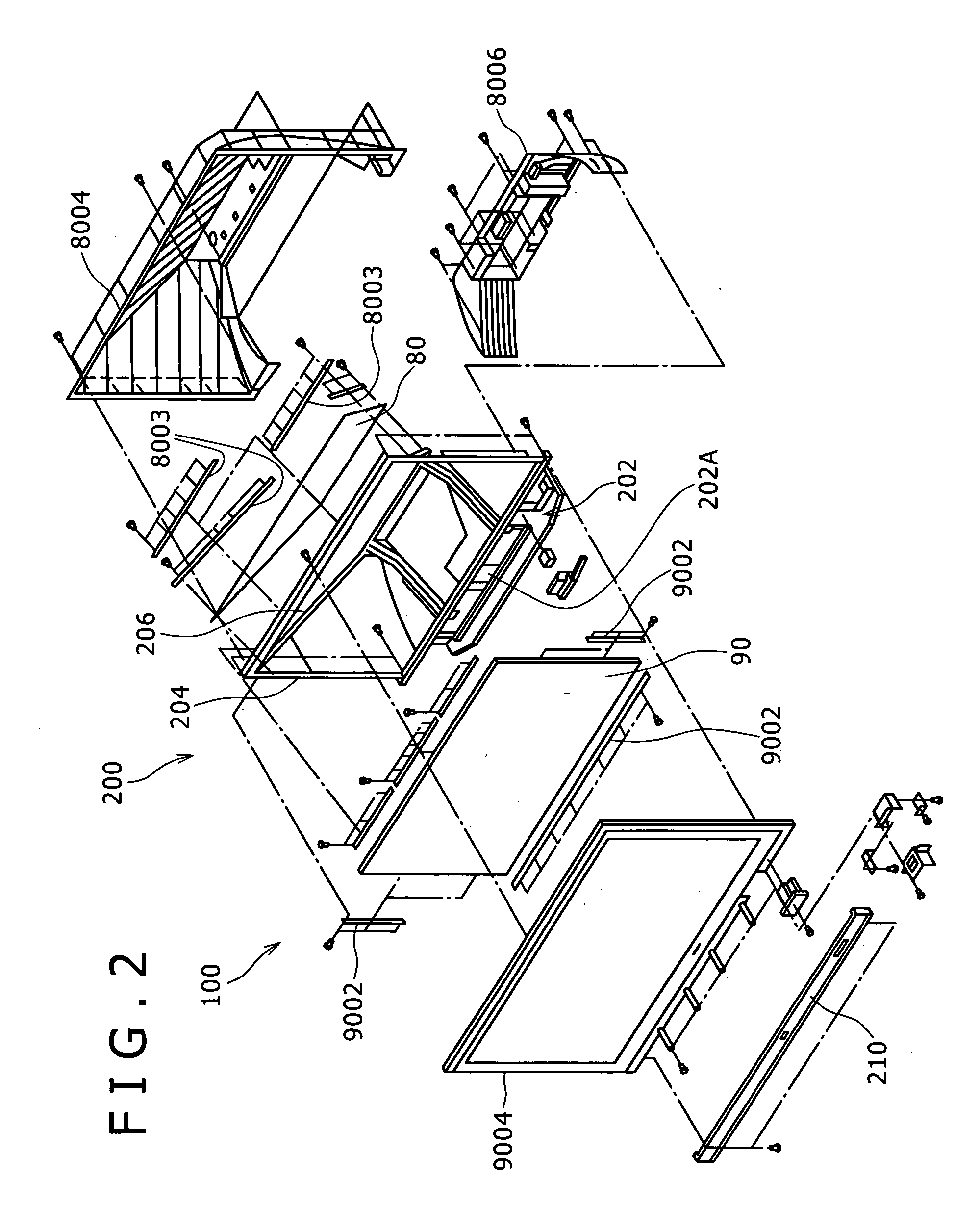
[0039] Referring to FIGS. 1A and 1B, the projection television apparatus 100 shown includes a frame 200 which in turn includes a projector unit 10, a reflecting mirror 80, and a screen 90 of the rear projection type.

[0040] The projector unit 10 emits an image projection light flux.

[0041] The reflecting mirror 80 has a reflecting face 8002 and is disposed above the projector unit 10 rearwardly of the screen 90 of the rear projection type such that the reflecting face 8002 thereof reflects the image projection light flux emitted from the projector unit 10 toward the rear face of the screen 90.

[0042] The screen 90 displays a television image on the front face thereof when the image projection ligh...


PUM


Abstract

A projector unit is disclosed wherein a replacing operation of a light source is simplified and the quality of an image can be assured advantageously. A locking mechanism is formed from engaging pins, engaging pawls and a spring. The engaging pins are provided on a housing portion of a body section. The engaging pawls are each supported at a bearing portion intermediate in an extending direction thereof for rocking motion on a light source section housing by a pivot. The engaging pawls have engaging grooves provided thereon for engaging with the engaging pins in a state wherein mating portions of the light source section housing and the body section housing are mated with each other. The spring extends between a rear face of an intermediate divisional member of the light source section housing and a connecting piece of the engaging pawl.

Description

CROSS REFERENCES TO RELATED APPLICATIONS [0001] The present invention contains subject matter related to Japanese Patent Application JP 2005-181081 filed in the Japanese Patent Office on Jun. 21, 2005, the entire contents of which being incorporated herein by reference. BACKGROUND OF THE INVENTION [0002] 1. Field of the Invention [0003] This invention relates to a projector unit and a projection television apparatus which uses a projector unit. [0004] 2. Description of the Related Art [0005] A projection television apparatus, that is, a rear projection television apparatus, is available wherein a flux of light is projected to the rear face of a screen of the rear projection type to form an image on the screen. [0006] Such a projection television apparatus as just described includes a projector unit which in turn includes a light source section including a light source and a body section for producing an image projection light flux from the light flux emitted from the light source se...

Claims


Application Information

Patent Timeline
IPC IPC(8): F21V29/00G01B11/24G03B21/56
CPCH04N5/7408G03B21/145G03B21/10H04N9/3141H04N5/74
Inventor MURASUGI, HIROSHI
Owner SONY CORP
Why Eureka
Try Eureka