Inkjet printing press

a printing press and inkjet technology, applied in the field of inkjet printing presses, can solve the problems of smudges or accidents, accurate printing, smudges on the print surface of sheets, etc., and achieve the effects of low rigidity, high quality printing, and small valu

Inactive Publication Date: 2011-03-22
KOTO HARUHIKO
View PDF15 Cites 45 Cited by
  • Summary
  • Abstract
  • Description
  • Claims
  • Application Information

AI Technical Summary

Benefits of technology

[0017]Also, according to a second aspect of the present invention, each clamp is a thin plate strip extending axially of the printing drum and the thickness of the clamps is set so that the sum of the thickness of each clamp and the thickness of the sheet is smaller than a gap defined between the outer peripheral surface of the printing drum and the inkjet head. This assures that the sheet can be held without interfering with the inkjet head.
[0025]Further, the clamp for holding the trailing end of the sheet is moved backward with respect to the rotating direction of the printing drum when it is moved from their open position to closed position, so that tension is imparted to the trailing end of the sheet by frictional force produced by contact with the clamp. Therefore the sheet can be held in a stable state with the entire sheet in close contact with the peripheral surface of the printing drum and thus extremely high quality printing is possible by inkjet.

Problems solved by technology

But, if the gap is too small, the sheet might contact the inkjet head, thus causing smudges or accidents.
Because this gap is normally extremely small, if the sheet is not held properly on the peripheral surface of the printing drum, accurate printing is impossible and the sheet can contact the inkjet head, thus causing smudges on the print surface of the sheet.
Thus, in printing a firm sheet, attraction at the sheet end tends to be insufficient, and if the sheet is thick, the sheet end tends to separate from the peripheral surface of the printing drum.
Also, in order to hold a sheet being fed at high speed, large static electricity is required.
This may cause electrical discharge with an inkjet press in which the inkjet head has to be provided in proximity to the printing drum.
Also, with the method of holding the sheet by negative pressure as disclosed in JP Patent 2868723, it is possible to attract the sheet onto the printing drum properly at a closed area such as at the center of the sheet, but at the peripheral portion of the sheet, because air is sucked from sheet ends, negative pressure cannot be maintained, so that sheet ends cannot be held effectively.
Further, if the sheet is absorptive such as paper, negative pressure applied to the sheet may cause the ink applied by the inkjet head to permeate into the sheet.
This results in change of ink color depending on the degree of permeation and makes it difficult to provide stable printing quality.
Thus, the sheet tends to be loose and lift off the drum surface, so that it is not possible to obtain a stable mounting state in which the entire sheet is in close contact with the drum surface.
But because it imparts tension by dividing a portion of the rotary drum corresponding to the trailing end of the sheet so as to be movable, it is not suited for use with general-purpose presses which print sheets of different sizes at high speed.
In this arrangement, it is difficult to assure a gap of proper size between the inkjet head and the peripheral surface of the printing drum.
But because it is adapted to clamp only part of the trailing end of the sheet, if the sheet supplied has a bent end, the clamp can not hold the sheet.
But in order to make smooth the drum surface on which divided sheets have to be held in a smooth state, a complicated mechanism requiring high accuracy is needed, and thus the device tends to be very expensive.

Method used


Image

  • Inkjet printing press
  • Inkjet printing press
  • Inkjet printing press

Examples


Embodiment Construction

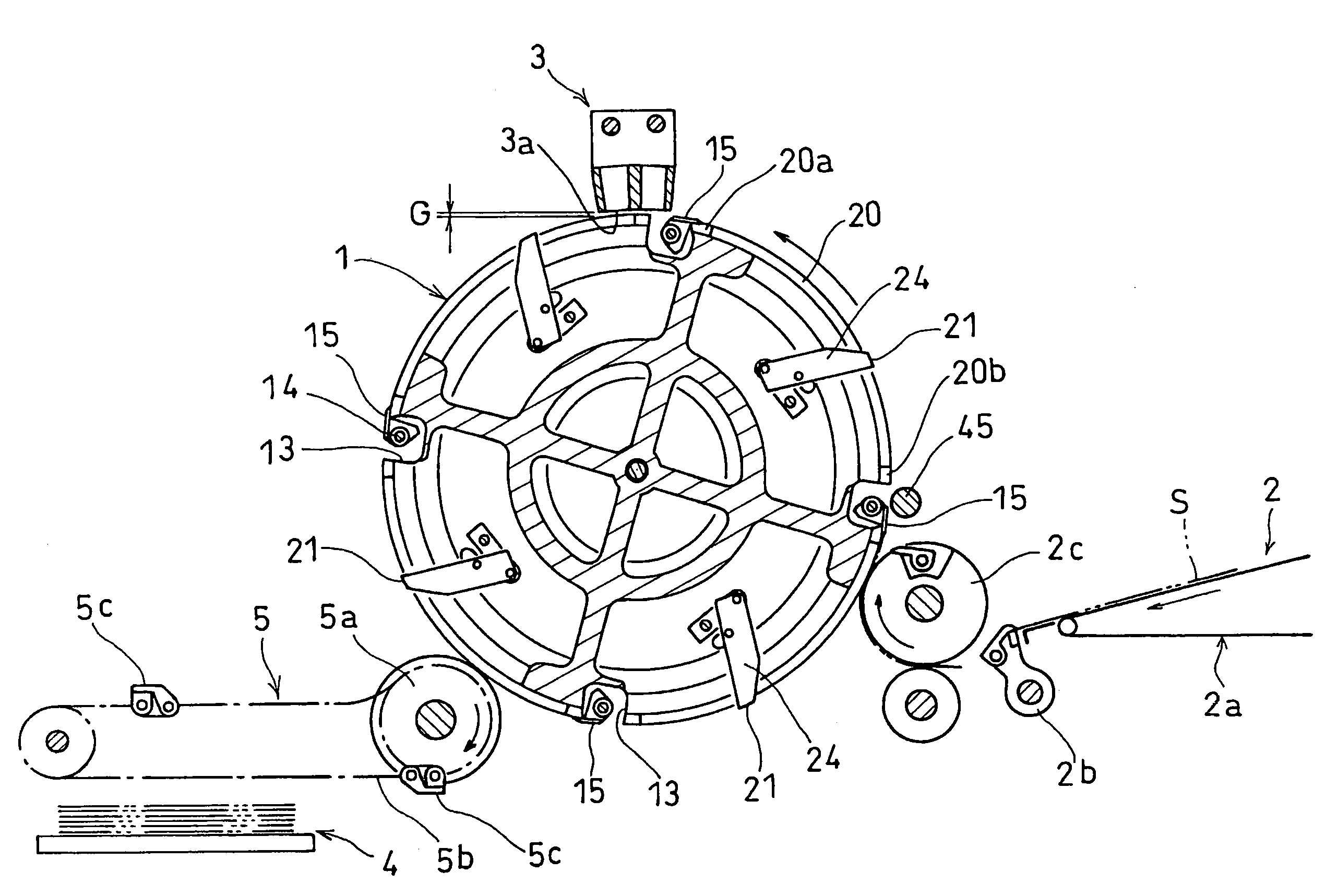
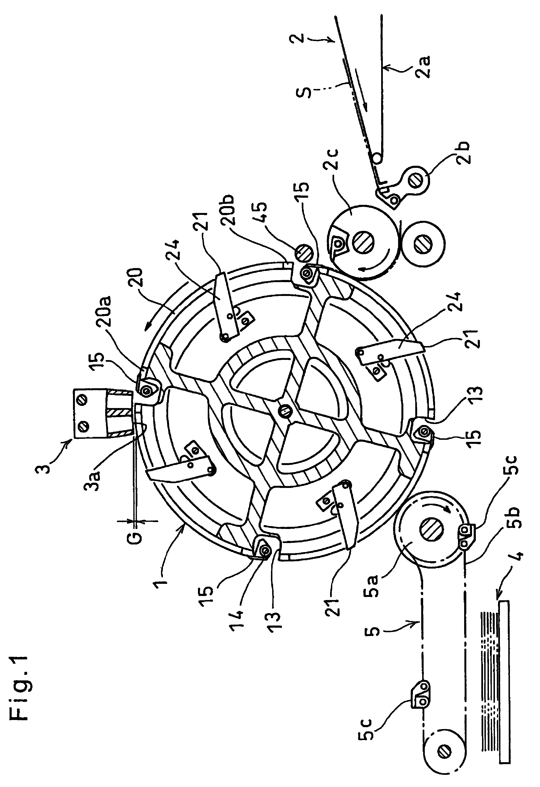
[0034]Now an embodiment of this invention is described with reference to the drawings. As shown in FIG. 1, the printing press according to the present invention includes a rotary printing drum 1, a sheet feeder 2 for feeding sheets S to the printing drum 1, an inkjet head 3 facing the outer periphery of the printing drum 1 to jet ink to sheets S held on the periphery of the printing drum 1 and fed circumferentially for printing, and a sheet discharge unit 5 for receiving the printed sheets S from the printing drum 1 and feeding them to a sheet discharge station 4.

[0035]The sheet feeder 2 feeds sheets S one after another in one direction on a sheet conveyor 2a, grips the tip of the sheet S fed to the discharge end of the sheet conveyor 2a by a pivotal end of a swing gripper 2b, and pivots the swing gripper 2b toward a transfer cylinder 2c which is rotating in one direction to deliver the sheets S from the swing gripper 2b to holding claws provided on the transfer cylinder 2c and then...


PUM


Abstract

An inkjet printing press is provided which can hold sheets extremely stably. In an inkjet printing press, an inkjet head 3 is provided at the outer periphery of a printing drum 1 rotated in one direction. The printing drum 1 is provided with holding claws 15 which are opened and closed to hold the leading end of the sheet S, and clamps 21 which can be opened and closed for clamping the trailing end of the sheet S. When the clamps 21 are moved from their open positions to their closed positions, the clamps 21 are moved backward with respect to the rotating direction of the printing drum 1 to impart a tensile force to the trailing end of the sheet S and tighten the sheet so that the trailing end of the sheet is held by a clamp 21 with the sheet in its tight state. Also, the clamp 21 is brought into contact with the periphery of the printing drum 1 by an attracting device to assure the holding of the sheet.

Description

BACKGROUND OF THE INVENTION[0001]1. Technical Field[0002]This invention relates to an inkjet printing press for printing sheets with inkjets.[0003]2. Background Art[0004]Inkjet printing presses are known which have an inkjet head provided at the outer periphery of a rotary printing drum to jet ink against a sheet held on the peripheral surface of the printing drum for printing.[0005]With such an inkjet printing press, the smaller the gap between the sheet and the inkjet head having a plurality of nozzles, the less the interference to ink dots jetted from the nozzles and thus the better the printing quality. But, if the gap is too small, the sheet might contact the inkjet head, thus causing smudges or accidents. Practically, the press is used with the inkjet head in proximity to the sheet to a limit where there is no trouble such as mechanical contact while the inkjet head and the sheet are moving relative to each other for printing. Because this gap is normally extremely small, if t...

Claims


Application Information

Patent Timeline
Patent Type & Authority Patents(United States)
IPC IPC(8): B41J2/01
CPCB41J13/223
Inventor KOTO, HARUHIKONAKANO, MASARUSANTO, HIROYUKISATAKE, OSAMUMIYAJI, MAKOTO
Owner KOTO HARUHIKO
Why Eureka
Try Eureka