Method for filling through hole

a technology of through hole and plated metal, which is applied in the direction of printed circuits, electrical devices, printed circuit aspects, etc., can solve the problems of difficult industrial use of the method of filling through hole with plated metal by such electrolytic plating, and the difficulty of delicate control of time and timing, so as to achieve the effect of reducing the time taken to complete the filling of the through hole with plated metal and being easy to use industrially

Inactive Publication Date: 2011-03-22
SHINKO ELECTRIC IND CO LTD
View PDF17 Cites 9 Cited by
  • Summary
  • Abstract
  • Description
  • Claims
  • Application Information

AI Technical Summary

Benefits of technology

Embodiments of the present invention provide a through hole filling method which can reduce time taken to complete filling of a through hole with a plated metal and is easy to use industrially.
As a result of that, according to the invention, combined with the fact that a related-art electrolytic plating apparatus can be appropriated as an electrolytic plating apparatus, time taken to complete filling of a through hole with a plated metal can be reduced and it is easy to use industrially.

Problems solved by technology

However, when plating filling of the through hole by the electrolytic plating is performed at the low current density, it takes a long time to complete the filling.
However, in this electrolytic plating, reverse electrolysis is applied and a part of the plated metal layer is peeled and it is necessary to hold polarization resistance of the inside of the through hole at the time of positive electrolysis lower than that of the vicinity of the opening, so that it is necessary to delicately control time and timing at which the reverse electrolysis is applied.
As a result of this, the method for filling the through hole with the plated metal by such electrolytic plating is actually difficult to use industrially combined with complication as an electrolytic plating apparatus.

Method used


Image

  • Method for filling through hole
  • Method for filling through hole
  • Method for filling through hole

Examples


Embodiment Construction

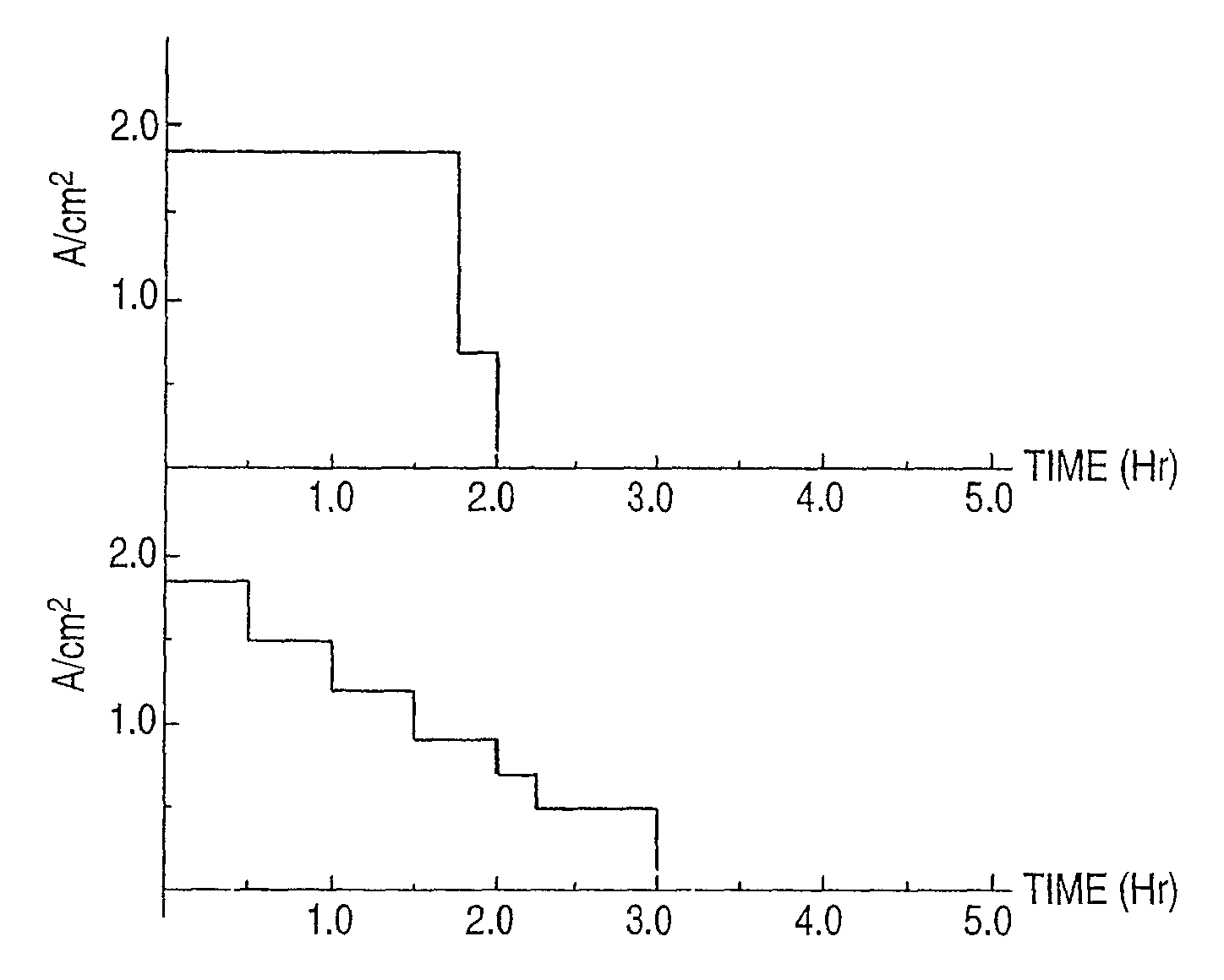
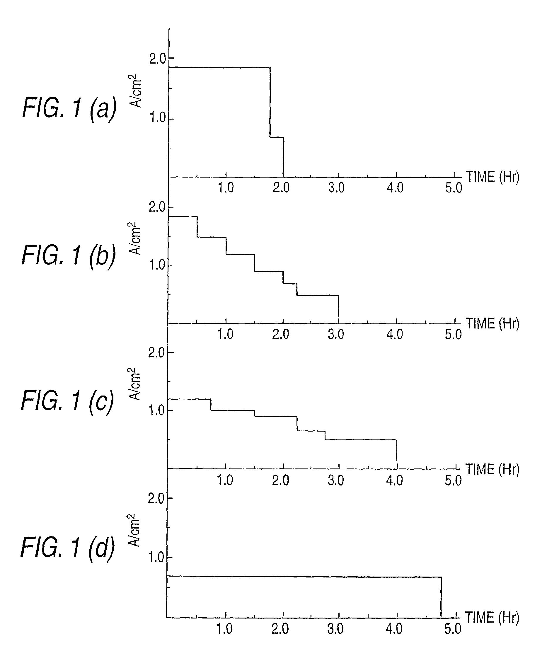
In the invention, it is necessary to start electrolytic plating by a high current density higher than Constant Current Density capable of fully filling a through hole when the electrolytic plating is performed with a current density held constant.

It is preferable that this Constant Current Density should be a current density in consideration of variations in the inside diameter etc. when plural through holes with the same diameter are formed in a substrate.

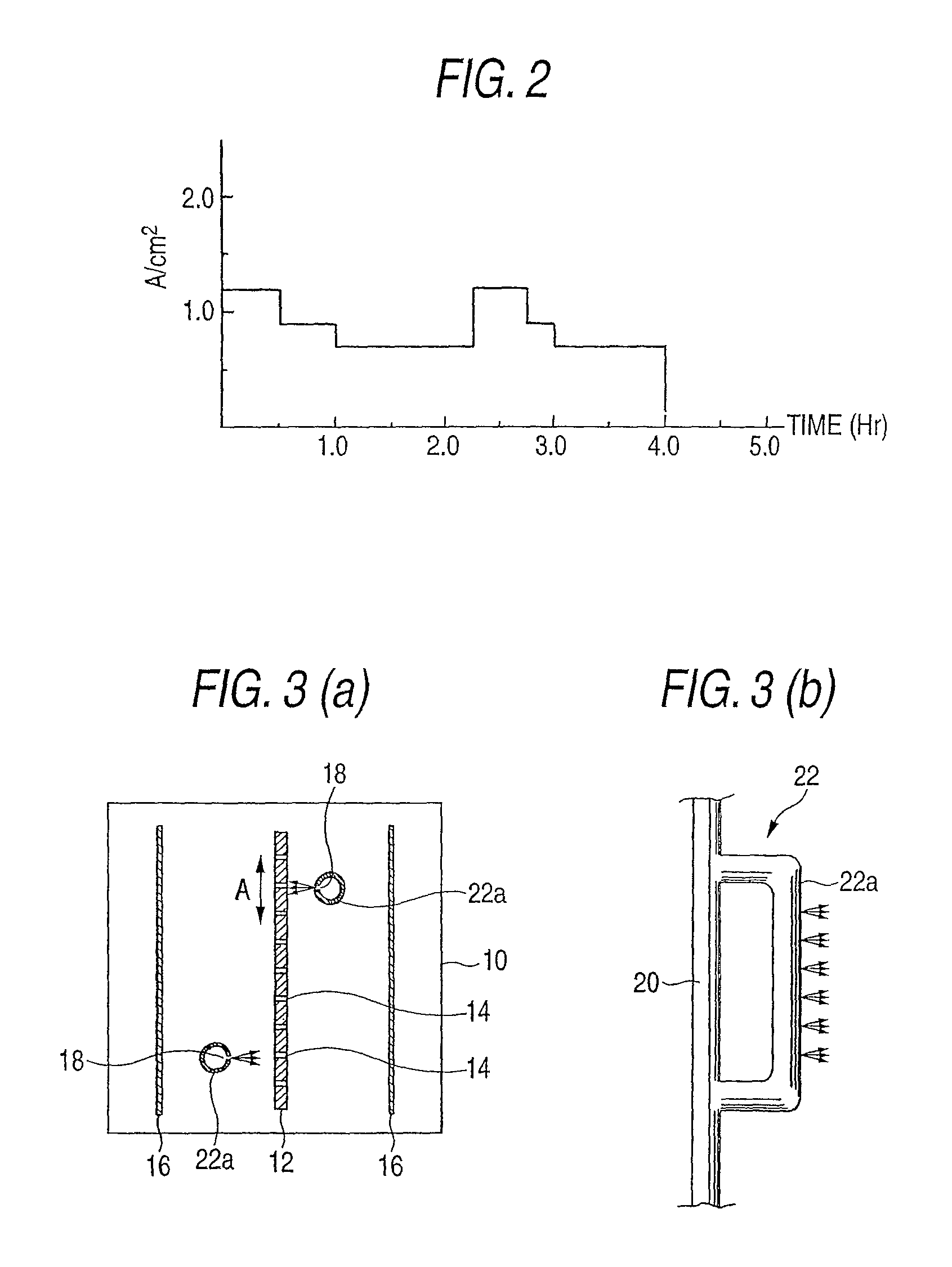
Also, it is preferable to adopt a high current density at which an initial value of throwing power represented by a ratio [(tin / tout)×100] between a thickness (tin) of a plated metal layer formed on an inner wall surface of a through hole and a thickness (tout) of a plated metal layer formed on a substrate surface in which this through hole is opened becomes 90% or more as the high current density higher than such Constant Current Density. In electrolytic plating of such a high current density, from the beginning of a start of the...


PUM


Abstract

It is characterized in that in the case of filling a through hole formed in a substrate with a plated metal by electrolytic plating, the electrolytic plating is started by a high current density higher than Constant Current Density capable of fully filling the through hole when the electrolytic plating is performed with a current density held constant as a current density of the electrolytic plating, and the electrolytic plating is continued by being changed to a current density lower than the high current density by the time of reaching formation of a seam diameter in which an inside diameter does not decrease even when the electrolytic plating is continued after the electrolytic plating at the high current density is started.

Description

TECHNICAL FIELDThe present disclosure relates to a method for filling a through hole, and more particularly to a through hole filling method for filling a through hole with a plated metal by electrolytic plating using a metal thin film with which the whole surface of a substrate in which the through hole is formed is covered as a power feeding layer.RELATED ARTIn a substrate used in an electronic component of a semiconductor device etc., a via extending through the substrate is formed and conductor patterns formed on both surfaces of the substrate are electrically connected.A formation method of such via includes, for example, a method for forming the via by filling a through hole extending through a substrate with a plated metal by electrolytic plating. This method is shown in FIG. 4. In the method shown in FIG. 4, after a cylindrical through hole 102 is first formed in a substrate 100 made of insulating material as shown in FIG. 4(a), a thin film metal layer 104 is formed on a sur...

Claims


Application Information

Patent Timeline
Patent Type & Authority Patents(United States)
IPC IPC(8): C25D5/18C25D5/02
CPCC25D5/026C25D5/18C25D17/02H05K3/423H05K3/426H05K2201/09563H05K2203/1476
Inventor MASHINO, NAOHIRO
Owner SHINKO ELECTRIC IND CO LTD
Why Eureka
Try Eureka