Confocal scanning endoscope system and image display area adjustment method thereof

a technology of endoscope and endoscope, which is applied in the field ofconfocal scanning endoscope system, can solve the problems of troublesome operation of operator, blurred peripheral part of observation image, and adverse effects on operator diagnosis

Inactive Publication Date: 2011-03-29
HOYA CORP
View PDF15 Cites 53 Cited by
  • Summary
  • Abstract
  • Description
  • Claims
  • Application Information

AI Technical Summary

Benefits of technology

The present invention is advantageous in that it provides a confocal scanning endoscope system capable of providing an observation image from which a blurred part caused by factors specific to the confocal scanning endoscope system is removed.
By adjusting the display area based on the measured Encircled Energy, it is possible to form the image based on the light passing through a part of the objective optical system having high resolution. In other words, it is possible to display a high quality image for observations not having a blurred region caused by factors specific to the confocal scanning endoscope system. Such a configuration enables an operator to conduct endoscopic observations.
With this configuration, it is possible to form the image based on the light passing through a part of the objective optical system having high resolution. In other words, it is possible to display a high quality image for observations not having a blurred region caused by factors specific to the confocal scanning endoscope system. Such a configuration enables an operator to conduct endoscopic observations.

Problems solved by technology

That is, the confocal observation requires the operator to conduct troublesome work in which removal of tissue and the observation of the tissue have to be conducted using separate apparatuses.
Therefore, resolution and brightness of a part of an image formed in the confocal scanning endoscope optical system by the light passing through the peripheral region of the confocal optical system decrease, and thereby a peripheral part of an observation image may become blurred.
If a blurred part appears on the observation image due to the above mentioned factors specific to the confocal scanning endoscope system, the diagnosis by the operator may be adversely affected.
However, downsizing an optical system leads to increasing the amount of off-axial aberration.
Further, if the confocal optical system has positional errors, such as decentering, the blurred part appears on the observation image in a shape asymmetric about an optical axis of the confocal optical system.
Such deterioration of the observation image may also adversely affect the diagnosis by the operator.

Method used


Image

  • Confocal scanning endoscope system and image display area adjustment method thereof
  • Confocal scanning endoscope system and image display area adjustment method thereof
  • Confocal scanning endoscope system and image display area adjustment method thereof

Examples


Embodiment Construction

Hereinafter, an embodiment according to the invention is described with reference to the accompanying drawings.

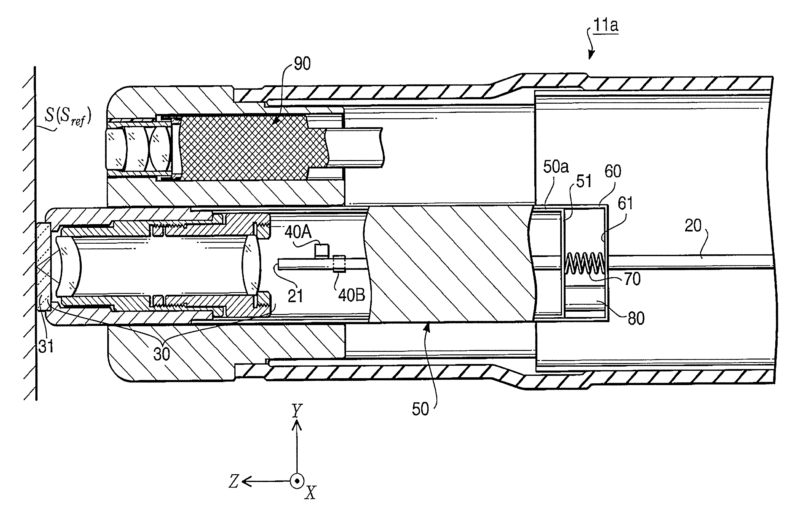
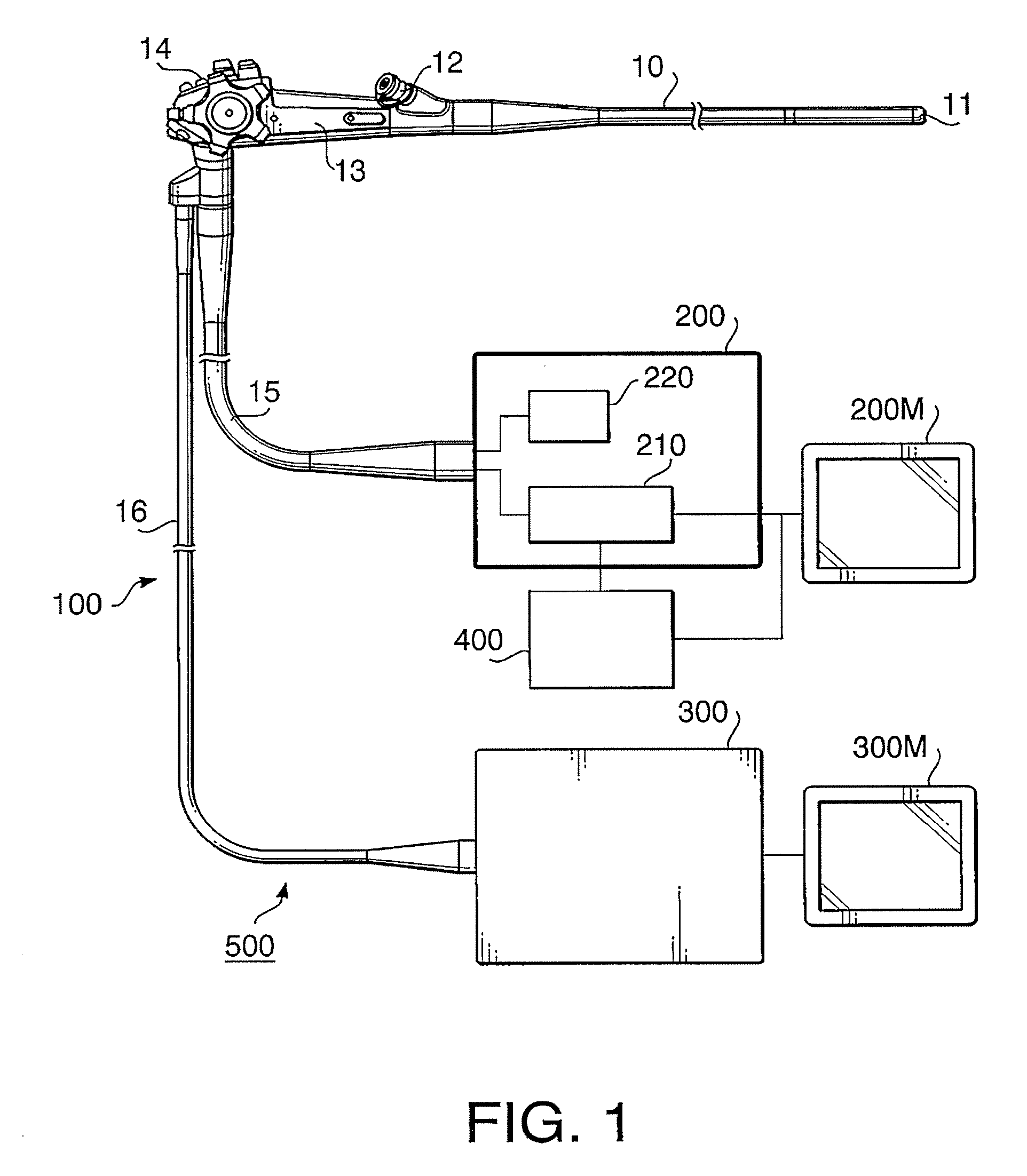
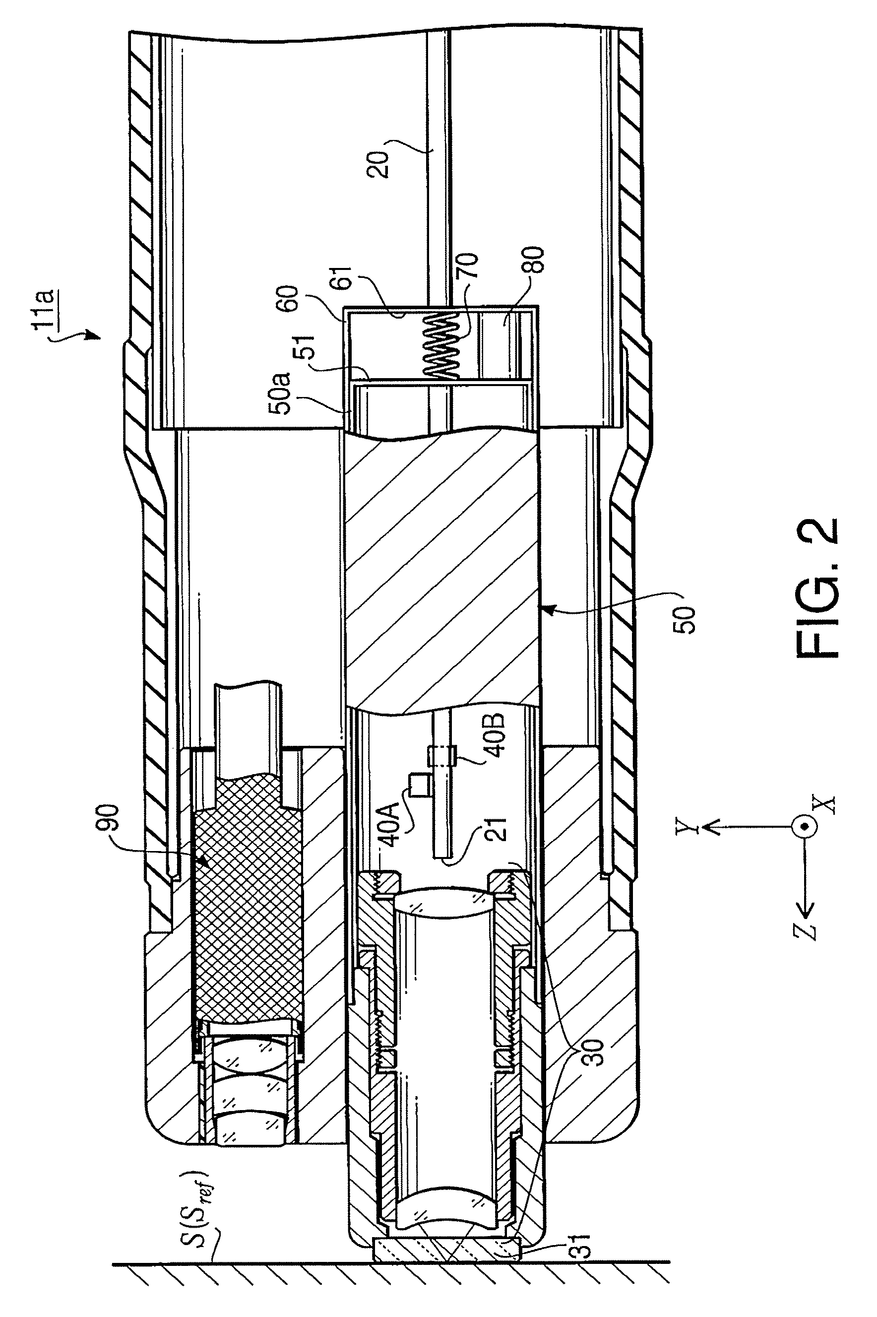
FIG. 1 is a block diagram of a confocal scanning endoscope system (hereafter, simply referred to as a confocal endoscope system) 500 according an embodiment of the invention. The confocal endoscope system 500 includes an electronic endoscope 100 having a flexible insertion tube 10 to be inserted into a body cavity to obtain an image of tissue in the body cavity, a processor 200 to which the electronic endoscope 100 is connected, a processor 300, a display area adjustment device 400 connected to the processor 200, and monitors 200M and 300M respectively connected to the processors 200 and 300. On the monitors 200M and 300M, images output by the processors 200 and 300 are displayed, respectively.

The electronic endoscope 100 has a confocal observation function of obtaining information concerning an image of tissue in a body cavity through use of a confocal optical system as we...


PUM


Abstract

There is provided a confocal scanning endoscope system, which is provided with a light source that emits light, a scanning unit that deflects the light emitted by the light source so that the light scans on a subject in two dimensions, an objective optical system that directs the light deflected by the scanning unit to the subject, an extraction unit that extracts only part of the light returning from a convergence point at which the light is converged by the objective optical system on an object side, an image formation unit configured to form an image based on the part of the light extracted by the extraction unit, and a display area adjustment unit configured to measure Encircled Energy of the part of the light extracted by the extraction unit and to adjust a display area of the image based on the measured Encircled Energy.

Description

BACKGROUND OF THE INVENTIONThe present invention relates to a confocal scanning endoscope system having a confocal observation function.Confocal scanning microscope systems capable of providing highly magnified high resolution images have been used. The confocal scanning microscope system is configured to emit a laser beam scanning on a sample in two dimensions. An operator of the confocal scanning microscope system observes the sample through a highly magnified high resolution observation image formed by the confocal scanning microscope system by illuminating the sample with the laser beam and receiving the laser beam from the sample through a pinhole positioned at a point conjugate with the sample. Examples of such a confocal scanning microscope system are disclosed in Japanese Patent Provisional Publications Nos. 2000-275528A and 2004-138947A.The above mentioned confocal microscope system requires an operator to remove part of tissue in a body cavity of a subject using an endosco...

Claims


Application Information

Patent Timeline
Patent Type & Authority Patents(United States)
IPC IPC(8): A61B1/06
CPCG02B21/0028
Inventor KANAI, MORIYASU
Owner HOYA CORP
Why Eureka
Try Eureka