
Device and method for remotely measuring and monitoring antenna system using mobile terminal

a mobile terminal and antenna system technology, applied in the direction of transmitter monitoring, instruments, transmission monitoring, etc., can solve the problems of large amount of cost generated by installing a vswr measurer in each base station, difficult to integrate management in consideration of the characteristics of the base station, and inability to determine the status of the antenna in real-time, so as to reduce efforts and maintenance fees

Active Publication Date: 2011-03-29
KT CORP
View PDF37 Cites 14 Cited by
  • Summary
  • Abstract
  • Description
  • Claims
  • Application Information

AI Technical Summary

Benefits of technology

[0016]It is an advantage of the present invention to provide a system and method for reducing efforts and maintenance fees caused by undesired antenna tests.
[0017]It is another advantage of the present invention to provide a system and method for remotely monitoring antenna systems of a base station and a repeater and managing the same in a combined manner.Technical Solution
[0018]In one aspect of the present invention, an antenna system monitor of a base station comprises: a radio communication module for receiving radio data including a first measurement value and a second measurement value of the antenna of the base station; a message parser for parsing the radio data to parse a base station identifier and measurement information; a base station information database for storing identifiers of a base station to be monitored, and status information of the base stations; a base station monitor for using the first and second measurement values to calculate factors of the base stations; and a measured result modifier for using status information of the base station information database corresponding to the base station identifier and modifying the calculated factors.
[0019]The first measurement value is a power of a progressive wave and the second measurement value is a power of a reflected wave.
[0020]In another aspect of the present invention, an antenna system measurer comprises: a first measurer for measuring a first measurement value of the antenna system; a second measurer for measuring a second measurement value of the antenna system; a radio data module for transmitting the first measurement value and the second measurement value in a radio data format; and a controller for controlling a number of measurement times of the first measurement value and the second measurement value and radio data transmission.
[0021]The first measurement value is a power of a progressive wave, and the second measurement value is a power of a reflected wave.

Problems solved by technology

In addition, a large amount of cost is generated for installing a VSWR measurer in each base station, integrated management in consideration of the characteristics of the base station is difficult, and it is impossible to determine the antenna's status in real-time.

Method used


Image

  • Device and method for remotely measuring and monitoring antenna system using mobile terminal
  • Device and method for remotely measuring and monitoring antenna system using mobile terminal
  • Device and method for remotely measuring and monitoring antenna system using mobile terminal

Examples


Embodiment Construction

[0030]In the following detailed description, only the preferred embodiment of the invention has been shown and described, simply by way of illustration of the best mode contemplated by the inventor(s) of carrying out the invention. As will be realized, the invention is capable of modification in various obvious respects, all without departing from the invention. Accordingly, the drawings and description are to be regarded as illustrative in nature, and not restrictive. To clarify the present invention, parts which are not described in the specification are omitted, and parts for which same descriptions are provided have the same reference numerals.

[0031]A device and method for remotely measuring an antenna system according to a preferred embodiment of the present invention will be described.

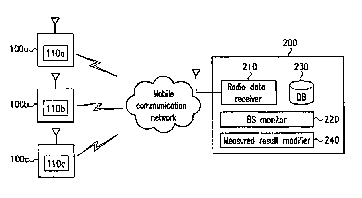
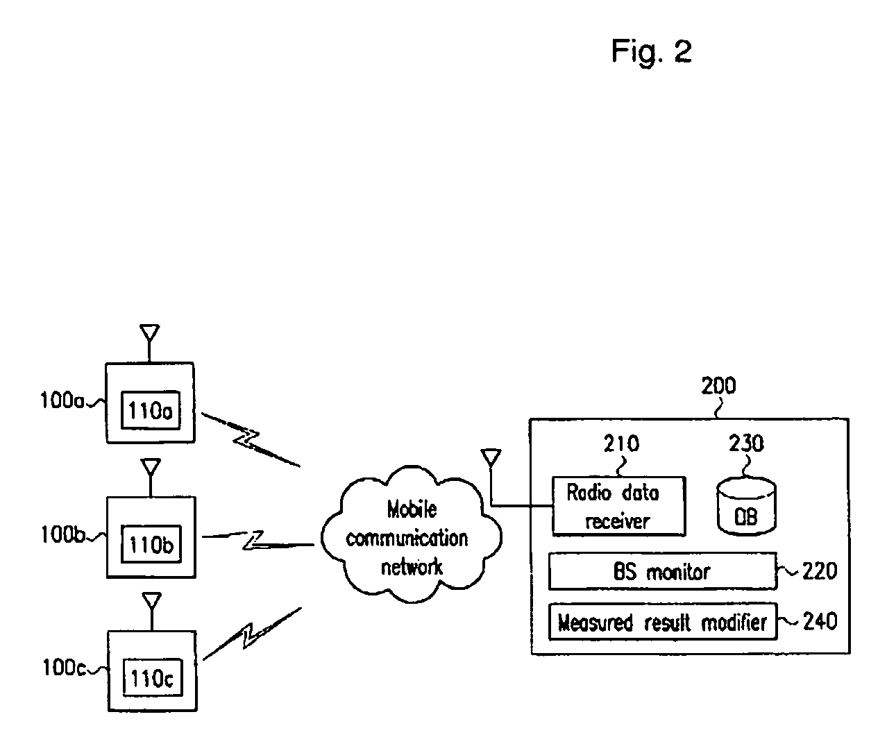
[0032]FIG. 2 shows a system for remotely measuring and monitoring an antenna system according to a preferred embodiment of the present invention.

[0033]The system includes a plurality of base stat...


PUM


Abstract

An antenna system measurer for a repeater and a base station measures powers of a progressive wave and a reflected wave of a transmit / receive antenna, and transmits measured results to a monitoring server in a radio data format such as an SMS message. The monitoring server receives the radio data, identifies a repeater and a base station from sender information of the radio data, and calculates a VSWR based on the measured values. The VSWR is modified based on characteristics of the base station such as length and substance of feeders from a base station identifier corresponding to the sender information. According to the present invention, the remote antenna system is monitored in real-time without visits or installation fees, and a plurality of repeaters and base stations is managed in a combined manner.

Description

TECHNICAL FIELD[0001]The present invention relates to a device and method for remotely measuring and monitoring an antenna system of a repeater or a base station. More specifically, the present invention relates to a system and method for measuring and monitoring the antenna of a remote repeater or base station without directly testing the antenna.BACKGROUND ART[0002]A base station or a repeater has an antenna for transmission and reception, and one test point for measuring the performance of the antenna is the voltage standing-wave ratio (VSWR).[0003]The VSWR represents a voltage ratio measured from an adjacent node and amplitude within a cable or a waveguide having a standing wave, or the VSWR denotes the ratio of maximum to minimum voltage in a standing wave pattern in a transmission line.[0004]For example, a progressive wave is divided into a progressive wave and a reflected wave on two media with two different kinds of impedance because of impedance mismatch, and the difference...

Claims


Application Information

Patent Timeline
Patent Type & Authority Patents(United States)
IPC IPC(8): H04M1/00H04Q7/34G01R27/06G01R29/10H04B17/00H04B17/40
CPCG01R27/06G01R29/10H04B17/40H04B17/18H04B17/103
Inventor SONG, JAE-SUBCHOI, JIN-HOKIM, JAE-KONLEE, JUNG-HO
Owner KT CORP
Learn More