Hair trimmer

a hair trimmer and hair technology, applied in the direction of metal working devices, etc., can solve the problems of making the cutting of hairs difficult through gaps, and achieve the effect of preventing cutting off hairs, smooth bringing in hairs for trimming, and simple structur

Inactive Publication Date: 2011-04-12
MATSUSHITA ELECTRIC WORKS LTD
View PDF25 Cites 14 Cited by
  • Summary
  • Abstract
  • Description
  • Claims
  • Application Information

AI Technical Summary

Benefits of technology

[0005]The present invention has been developed to solve the above-described conventional problems of the conventional hair trimmer discussed above. Accordingly, an object of the present invention is to provide a hair trimmer having a simple structure capable of controlling and preventing cut-off hairs from scattering out randomly and being dispersed into the surrounding area while smoothly bringing in hairs for trimming. Thus, hairs can get in through the hair introducing gaps just as easily as the conventional hair trimmer, but cut-off hairs' getting out through the gaps is made much more difficult.
[0006]In accordance with the present invention, there is provided a hair trimmer including: a main body; a cutter block having a stationary blade and a movable blade, both of which are comb-shaped and are slidably in contact with each other, the cutter block being protrudingly installed at one end of the main body; and a comb attachment having a plurality of comb tooth-shaped sections and covering the cutter block, wherein the comb tooth-shaped sections are provided with cut-off hair deflectors to prevent hairs cut by the cutter block from outwardly scattering away from the comb attachment, cut-off hair deflectors located between two neighboring comb tooth-shaped sections are disposed at relatively inner and outer positions.

Problems solved by technology

Thus, hairs can get in through the hair introducing gaps just as easily as the conventional hair trimmer, but cut-off hairs' getting out through the gaps is made much more difficult.

Method used


Image

  • Hair trimmer
  • Hair trimmer
  • Hair trimmer

Examples


Embodiment Construction

[0024]Hereinafter, preferred embodiments of the hair trimmer in accordance with the present invention will be described with reference to the accompanying drawings.

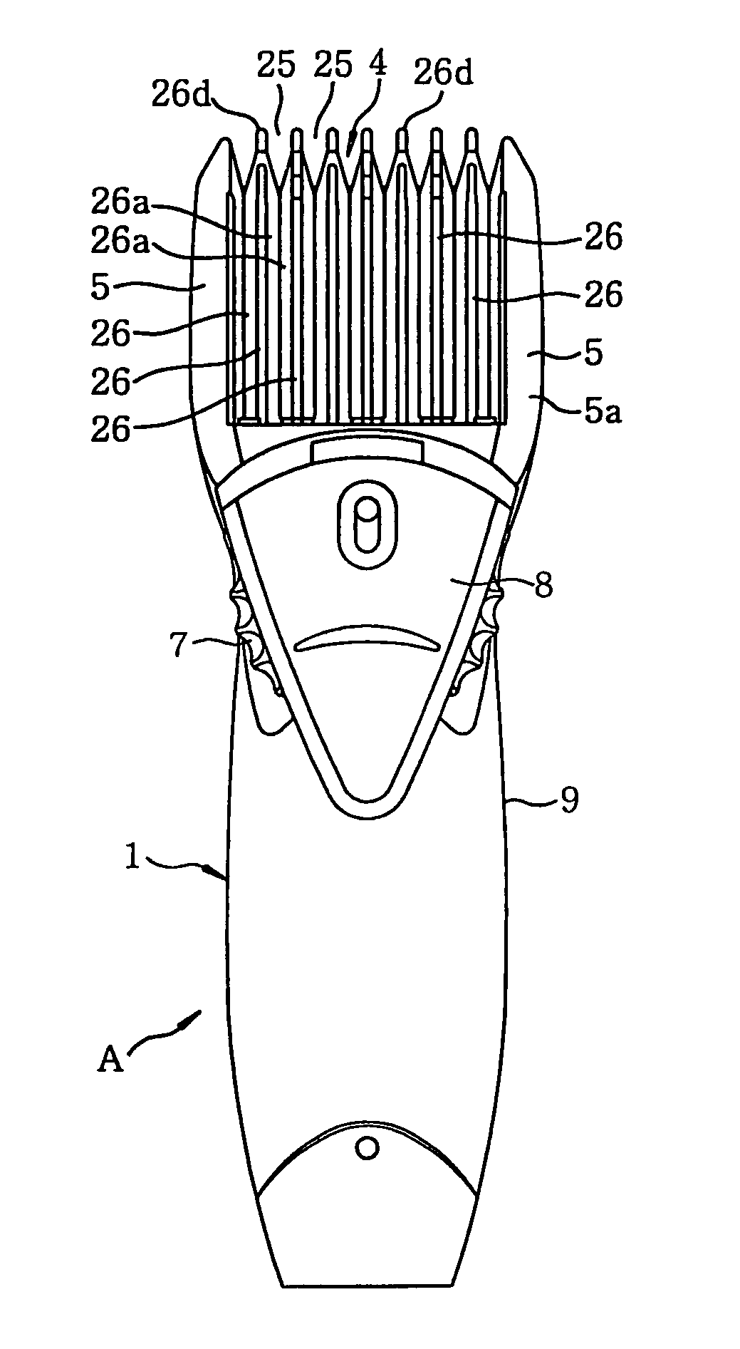
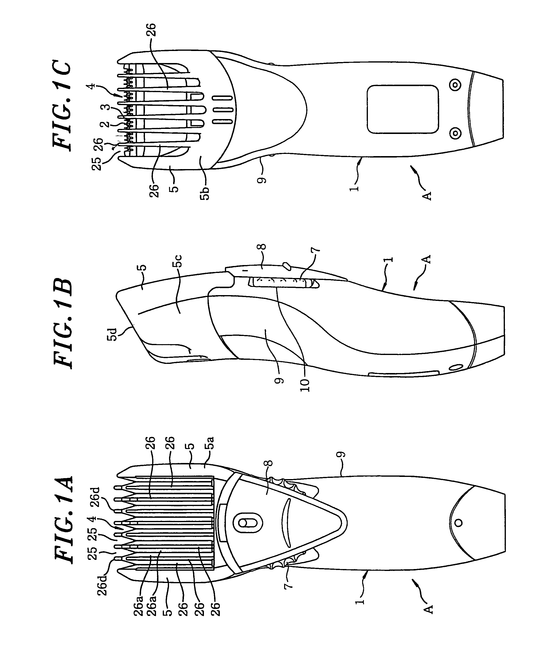
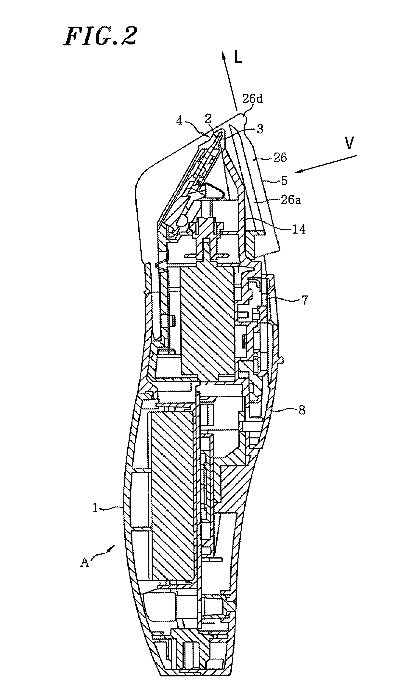
[0025]A hair trimmer A is constructed in such a way that a cutter block 4 having a stationary blade 2 in combination with and a movable blade 3, which is movable in a sliding direction S that extends into and out of the page when viewing FIG. 2, both of which are comb-shaped and slidably in contact with each other, is protrudingly disposed at one end portion in the lengthwise direction of an approximately cylindrical main body 1 which extends from the one end to the other end portion. A comb attachment 5 for trim length adjustment, having a plurality of comb tooth-shaped sections 26, movably covers the cutter block 4 along a projected direction of the cutter block 4.

[0026]The hair trimmer is configured as follows in order that the comb attachment 5 is installed to movably cover the cutter block 4 along the projected direc...


PUM


Abstract

A hair trimmer includes a main body, a cutter block and a comb attachment. The cutter block has a stationary blade and a movable blade, both of which are comb-shaped and are slidably in contact with each other. In addition, the cutter block is protrudingly installed at one end of the main body. The comb attachment has a plurality of comb tooth-shaped sections and covers the cutter block. The comb tooth-shaped sections are provided with cut-off hair deflectors to prevent hairs cut by the cutter block from outwardly scattering away from the comb attachment. Furthermore, cut-off hair deflectors located between two neighboring comb tooth-shaped sections are disposed at relatively inner and outer positions.

Description

FIELD OF THE INVENTION[0001]The present invention relates to a hair trimmer; and, more particularly, to a technique for preventing cut-off hairs from scattering out when hairs or beards brought in from a comb tooth-shaped section of a comb attachment covering a cutter block is cut by a stationary blade and a movable blade, both of which are comb-shaped and are slidably in contact with each other.BACKGROUND OF THE INVENTION[0002]Japanese Patent Laid-open Application No. H1-214388 (hereinafter refer to as “Patent 1”) discloses therein a trim length adjusting structure for a conventional hair trimmer. In the conventional example described in Patent 1, a cutter block consisting of a stationary and a movable blade, both of which are comb-shaped and slidably in contact with each other, is protrudingly disposed at one end portion of a main body. A cylindrical comb attachment for trim length adjustment, having a plurality of comb tooth-shaped sections, is movably engaged at the portion of t...

Claims


Application Information

Patent Timeline
Patent Type & Authority Patents(United States)
IPC IPC(8): B26B19/20B26B19/02B26B19/06B26B19/42B26B19/44
CPCB26B19/20B26B19/06B26B19/02B26B19/42B26B19/44
Inventor YAMAGUCHI, TAKASHIOGAWA, HITOSHI
Owner MATSUSHITA ELECTRIC WORKS LTD
Why Eureka
Try Eureka