Plastic encapsulated energetic material initiation device

a technology of energetic materials and initiators, which is applied in the direction of electric fuzes, weapons, ammunition fuzes, etc., can solve the problems of not being used in many applications, not being susceptible to improvement, and being difficult and labor-intensive to fabrica

Active Publication Date: 2011-04-12
REYNOLDS SYST
View PDF51 Cites 17 Cited by
  • Summary
  • Abstract
  • Description
  • Claims
  • Application Information

AI Technical Summary

Problems solved by technology

While modern initiator configurations are generally satisfactory for their intended purposes, they are nonetheless susceptible to improvement.
For example, many of these initiators, particularly those that employ exploding foil initiators, are relatively difficult and labor-intensive to fabricate.
Consequently, they are relatively expensive and are not employed in many applications due to considerations for cost.
Consequently, configurations employing multiple conventionally-configured detonator-type initiators do not provide maximum efficiency as the densities of the materials that are used in their construction are significantly different than that of the secondary explosive that is typically employed in a main explosive charge so that significant perturbations in the wave front are generated as the wave front passes through the detonator-type initiator and into (or back into) the main explosive charge.

Method used


Image

  • Plastic encapsulated energetic material initiation device
  • Plastic encapsulated energetic material initiation device
  • Plastic encapsulated energetic material initiation device

Examples


Embodiment Construction

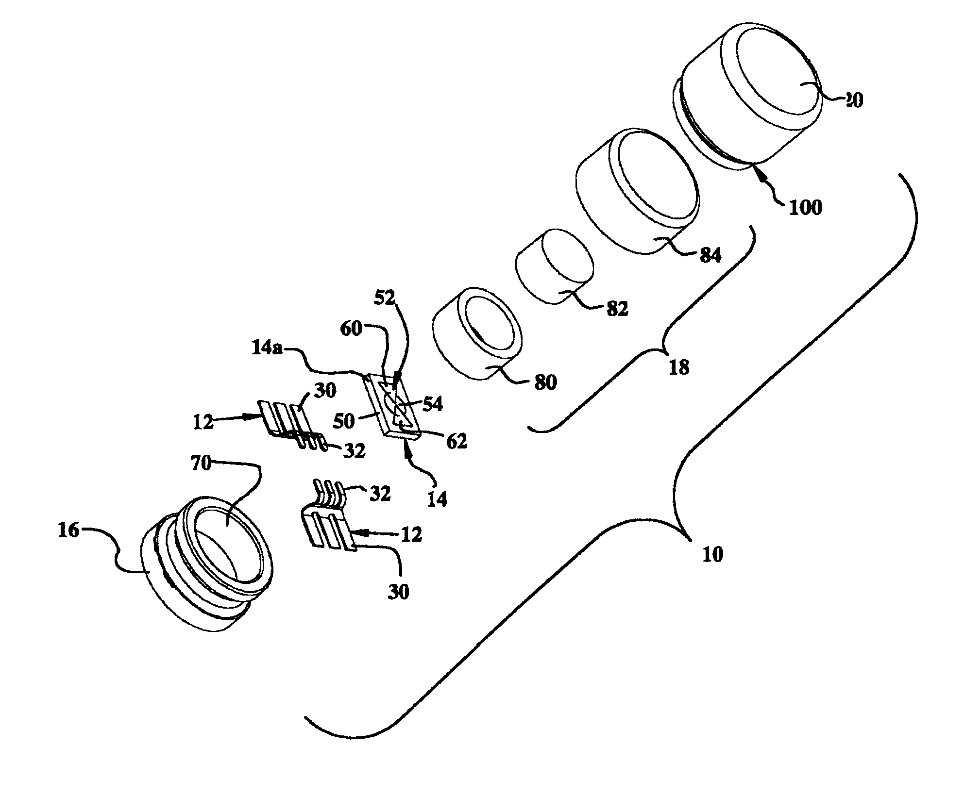
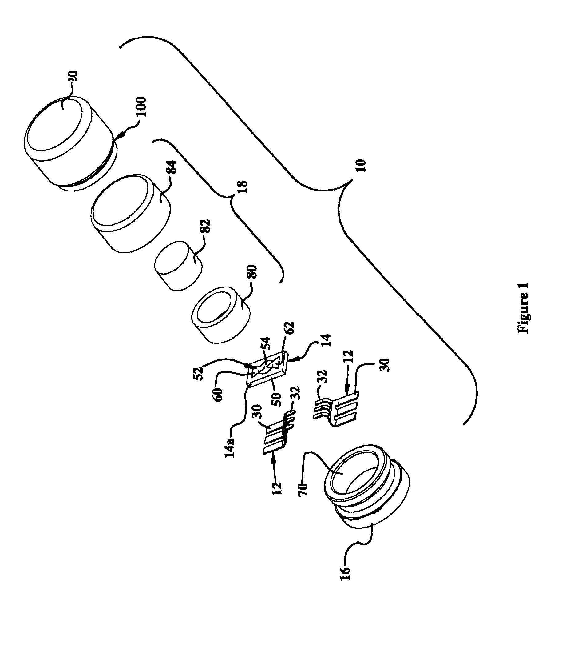
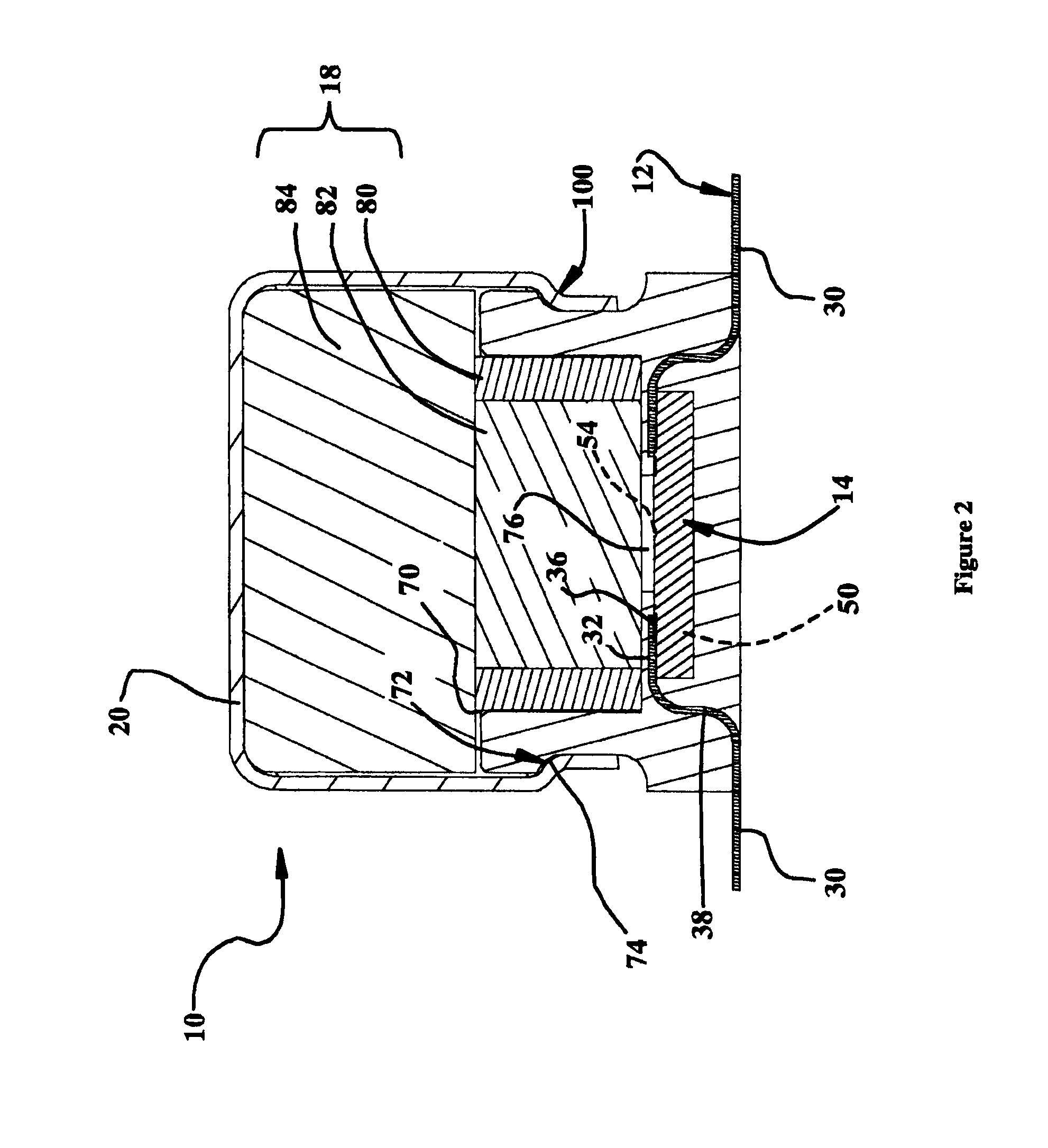
[0029]With reference to FIGS. 1 and 2 of the drawings, an initiator constructed in accordance with the teachings of the present invention is generally indicated by reference numeral 10. While the initiator 10 is illustrated as being a detonator-type initiator, the initiator 10 may be any type of initiator and may be configured to initiate a combustion event, a deflagration event and / or a detonation event. The initiator 10 may include a plurality of electrical contacts 12, an initiator chip 14, a housing 16, a pellet assembly 18.

[0030]With additional reference to FIG. 3, the electrical contacts 12 may be formed as a portion of a lead frame 24. The lead frame 24 may be configured to support the initiator chip 14 during the fabrication of the initiator 10 and may be formed from any appropriate material. In the particular example provided, the initiator chip 14 is electronically-actuated and as such, the lead frame 24 may be fully or partially formed of an electrically conductive materi...


PUM


Abstract

An initiator with a housing formed of plastic and a chip assembly for initiating at least one of a combustion event, a deflagration event and a detonation event. The chip assembly includes an electrically-actuated chip and a pair of electric leads that extend through the housing and are configured to couple the electrically-actuated chip to a fireset circuit. The electrically-actuated chip is partially encapsulated in the housing. A method for forming an initiator is also provided.

Description

[0001]This application is a division of U.S. patent application Ser. No. 12 / 468,957, filed May 20, 2009, which is a division of U.S. patent application Ser. No. 10 / 829,970 filed Apr. 22, 2004, issued as U.S. Pat. No. 7,690,303 on Apr. 6, 2010, the disclosures of which are hereby incorporated by reference as if fully set forth in detail herein.INTRODUCTION[0002]The present invention generally relates to devices for initiating combustion, deflagration and detonation events.[0003]Modern initiators, such as detonators, commonly employ materials including ceramics and stainless steels in their construction. These materials are typically selected to provide the initiator with a degree of robustness that permits the initiator to withstand extreme changes in temperature and humidity, as well as to resist oxidization. While modern initiator configurations are generally satisfactory for their intended purposes, they are nonetheless susceptible to improvement.[0004]For example, many of these i...

Claims


Application Information

Patent Timeline
Patent Type & Authority Patents(United States)
IPC IPC(8): F42C19/14F42B3/198F42B3/12F42C11/00
CPCF42B3/121
Inventor REYNOLDS, RICHARD K.NANCE, CHRISTOPHER J.CUNNINGHAM, ANDREW F.
Owner REYNOLDS SYST
Why Eureka
Try Eureka