
Device for locking and releasing a screw bit

a screw bit and screw technology, applied in the direction of chucks, mechanical instruments, manufacturing tools, etc., can solve the problems of dangerously powerful magnetized bits springing out of the bit holder, and achieve the effect of convenient assembly, simple installation, and safe unloading

Inactive Publication Date: 2011-04-12
MENG CHI FEN
View PDF17 Cites 50 Cited by
  • Summary
  • Abstract
  • Description
  • Claims
  • Application Information

AI Technical Summary

Benefits of technology

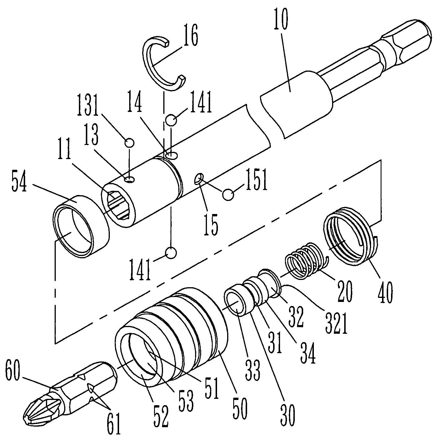
"The screwdriver bit holder structure described in this patent is designed to make installation easier and safer. It allows for smooth and tight fixation of driver bits into the holder body, and also prevents powerful ejection during unloading. The structure includes a holder body with a polygon hole for loading bits and a cylinder cavity for housing a spring and sliding tube. A c-clamp clips the holder body and front balls fit into concaves on the bits to fix or loose them. A fixing cap is capped on the holder body, and a limiting ring is set at the back of the cap to push the front balls into the fitting concaves of the bits. An outer spring is also installed between the back recess and c-clamp. Overall, this structure ensures easy assembly, tight or loose fixation of bits, and safe unloading."

Problems solved by technology

Although driver bits can be fixed in the polygon hole tightly based on aforementioned structure, it may cause safety concern because the spring component fixed in the fixing plate will suddenly and fully release accumulated power, then pushes fixing plate move outwards rapidly, which further forces the magnetized bits to spring out of the bit holder too powerfully to a dangerous extent when the bits are released by pushing down the ring until the top and bottom balls can leave the concaves of the bits and the triangle recess of fixing plate.

Method used


Image

  • Device for locking and releasing a screw bit
  • Device for locking and releasing a screw bit
  • Device for locking and releasing a screw bit

Examples


Embodiment Construction

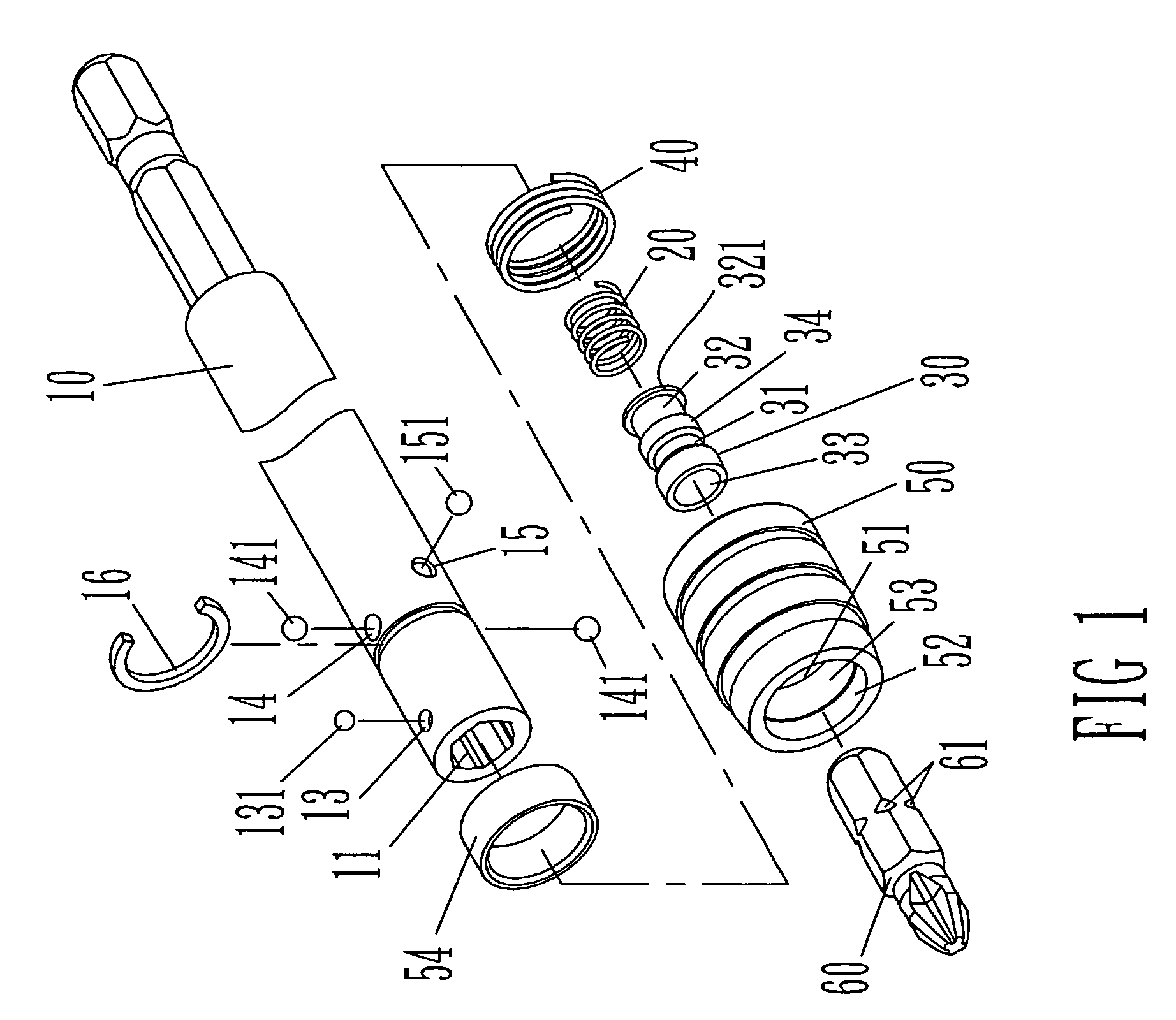
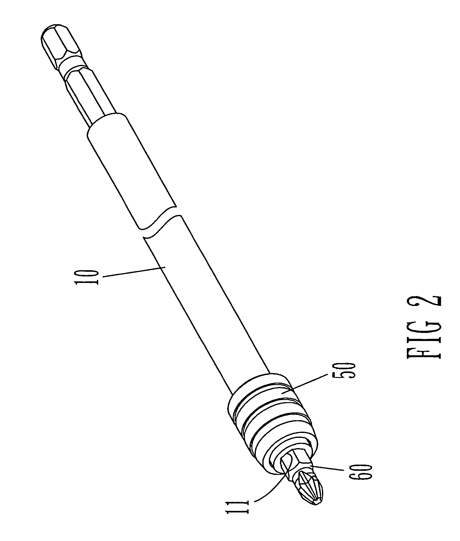
[0013]Please read the description of an exemplary embodiment as follows with references to FIGS. 1 and 2. The invention proposes a screwdriver bit holder structure, which comprises: a holder body 10 that sets a polygon hole 11 in one end in shaft axis, and at the end of the polygon hole sets a cylinder cavity 12 in the same axis of center as polygon hole. In the same end polygon hole set front ball holes 13, middle ball holes 14, and back ball holes 15 in order that penetrate into the polygon hole 11 and the cylinder cavity 12. The ball holes 13, 14, 15 are filled with front balls 131, middle balls 141, and back balls 151 respectively; A c-clamp 16 is clipped externally around the polygon hole 11, and it is positioned between front ball holes 13 and middle ball holes 14; An inner spring 20 and a sliding tube 30 are set inside the cylinder cavity 12, and the sliding tube has front groove 31 and back groove 32 externally. The middle balls 141 and back balls 151 are contained in either...


PUM


Abstract

A screwdriver bit holder structure, whose holder body has a polygon hole, and inside the polygon hole set an inner spring and a sliding tube. The holder body is clipped by a c-clamp, ahead of which are symmetric front balls and holes, and behind which are symmetric middle and back balls and holes. A fixing cap is capped on the holder body. In the back of inner hole of the fixing cap sets a limiting ring, and in the front sets a front recess and a back recess that is designed, by sliding the cap forward and backward along the holder body, to push front balls to fit into the fitting concaves of the bits so as to fix them tightly with the holder body or loose front balls from fitting concaves to release the bits.

Description

FIELD OF THE INVENTION[0001]This invention is to introduce a screwdriver bit holder structure, which can prevent driver bits from springing out unexpectedly while being unloaded.BACKGROUND OF THE INVENTION[0002]A prior art was proposed as Taiwan Patent No. M293121 “Screwdriver Bit Holder Structure (1)”, which comprises a screwdriver bit holder that has a polygon hole allowing load or unload of a driver bit, and at least a shaft-axis hole on top of it allowing balls to fit in; a ring clipped on the holder body externally, pushed by a spring component that is set between the ring and the holder body, and its inner part has a pressing wall used to push balls to fix bits. Its features include: at least one shaft-axis hole at the lower part of the holder body for balls to fit in, and a cylinder cavity at the inner part of the polygon hole. A spring component and fixing plate are set inside the cylinder cavity, and the fixing plate has a triangle recess facing the shaft-axis hole. The rin...

Claims


Application Information

Patent Timeline
Patent Type & Authority Patents(United States)
IPC IPC(8): B23B31/107
CPCB25B15/001B25B23/0035Y10T279/17752Y10S279/905Y10T279/3406Y10S279/906Y10T279/17196
Inventor MENG, CHI-FEN
Owner MENG CHI FEN
Learn More