LED module

a technology of led modules and led modules, applied in the field of led modules, can solve the problems of not being able to meet the requirements of round light patterns provided by conventional led modules, and not being able to illuminate a certain location

Inactive Publication Date: 2011-04-12
FU ZHUN PRECISION IND SHENZHEN +1
View PDF3 Cites 19 Cited by
  • Summary
  • Abstract
  • Description
  • Claims
  • Application Information

AI Technical Summary

Benefits of technology

[0005]Known implementations of LED modules in an LED lamp employ lenses for focusing light generated by the LEDs. However, a light pattern provided by such LED module is substantially round, which is not suitable for illuminating a certain location, such as roadway. For a roadway, it is required that the light generated by the lamp is directed along the extending direction of the roadway and altogether illuminates a road surface of the roadway. It is preferable that the light is prevented from lighting on a region neighboring a roadside of the roadway, such as houses beside the roadway. Apparently, the round light pattern provided by the conventional LED modules can not satisfy such a requirement.

Problems solved by technology

However, a light pattern provided by such LED module is substantially round, which is not suitable for illuminating a certain location, such as roadway.
Apparently, the round light pattern provided by the conventional LED modules can not satisfy such a requirement.

Method used


Image

  • LED module
  • LED module
  • LED module

Examples


Embodiment Construction

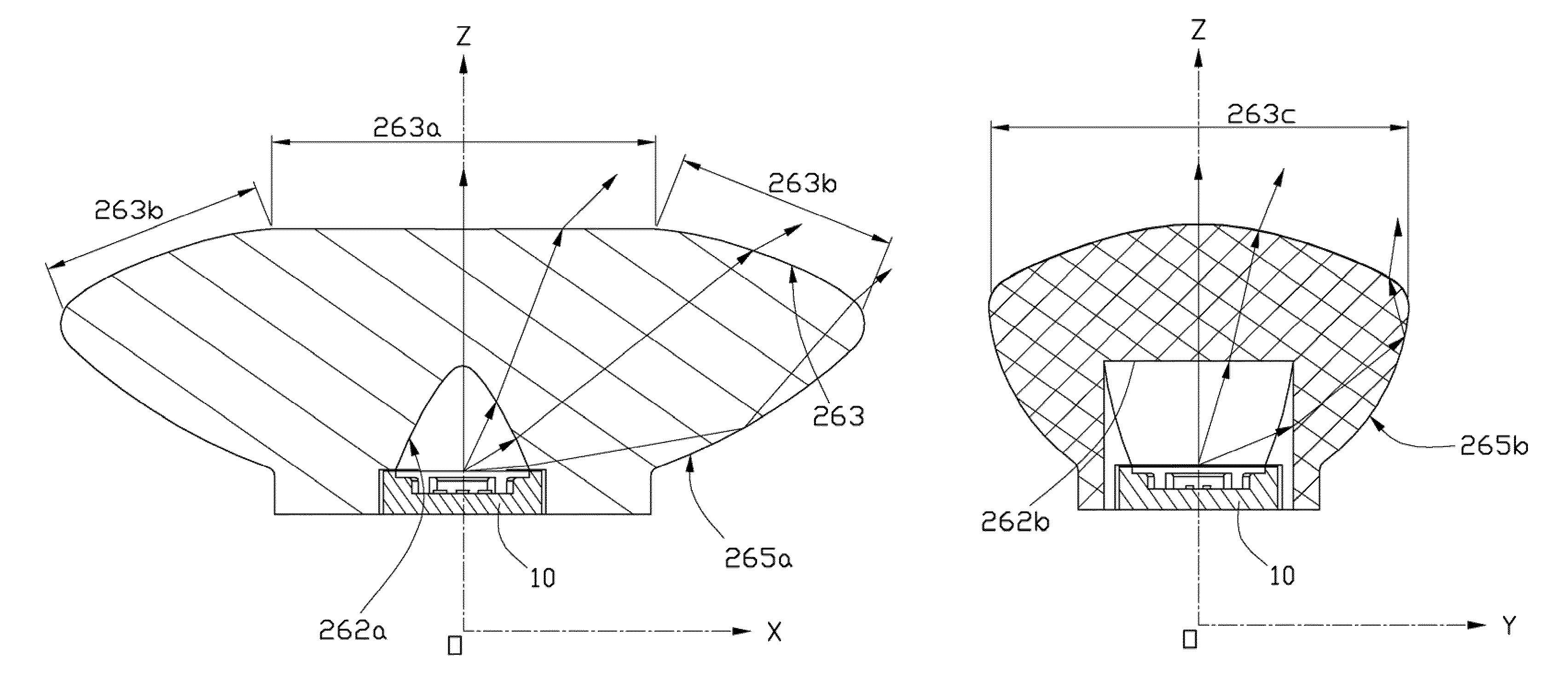
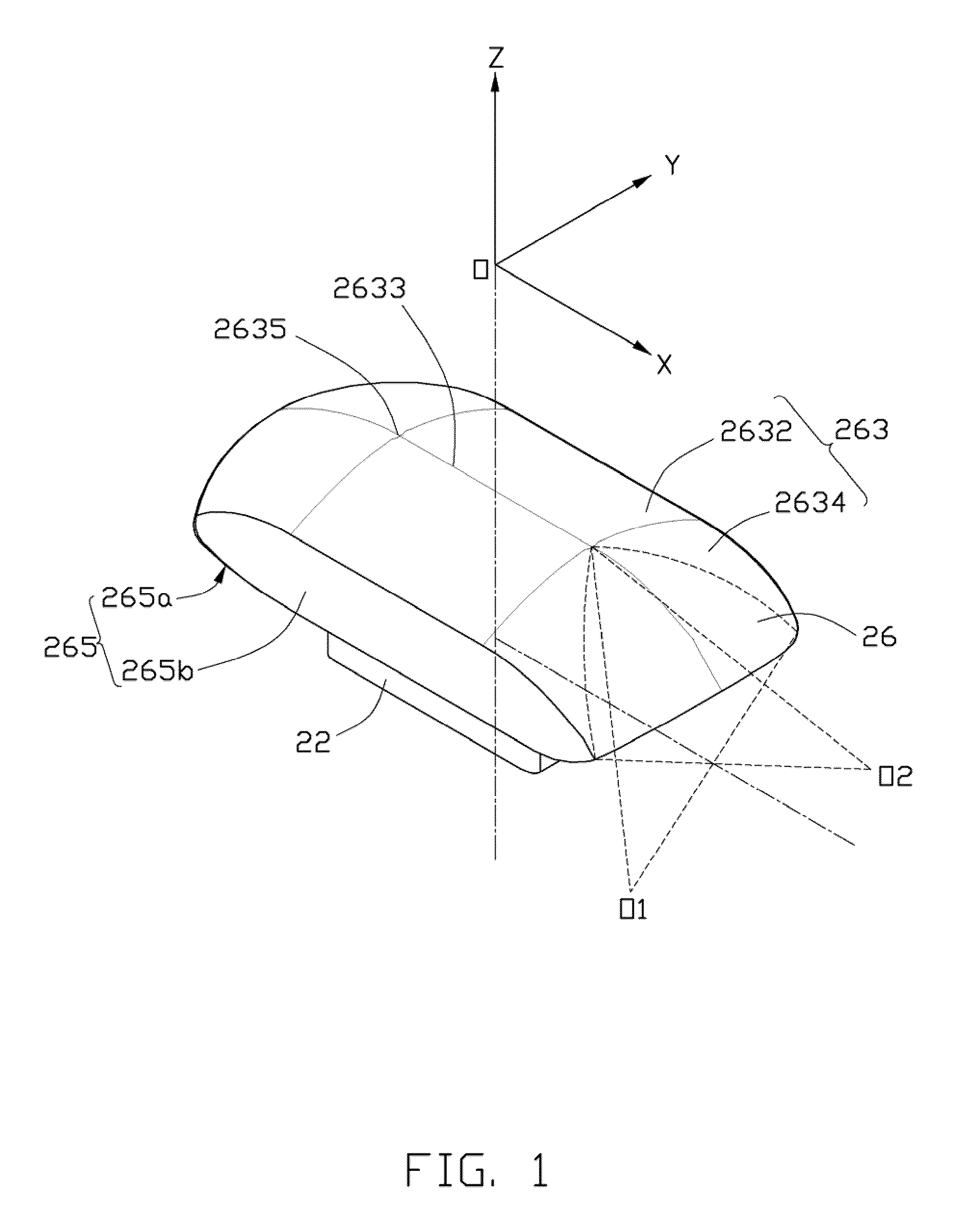
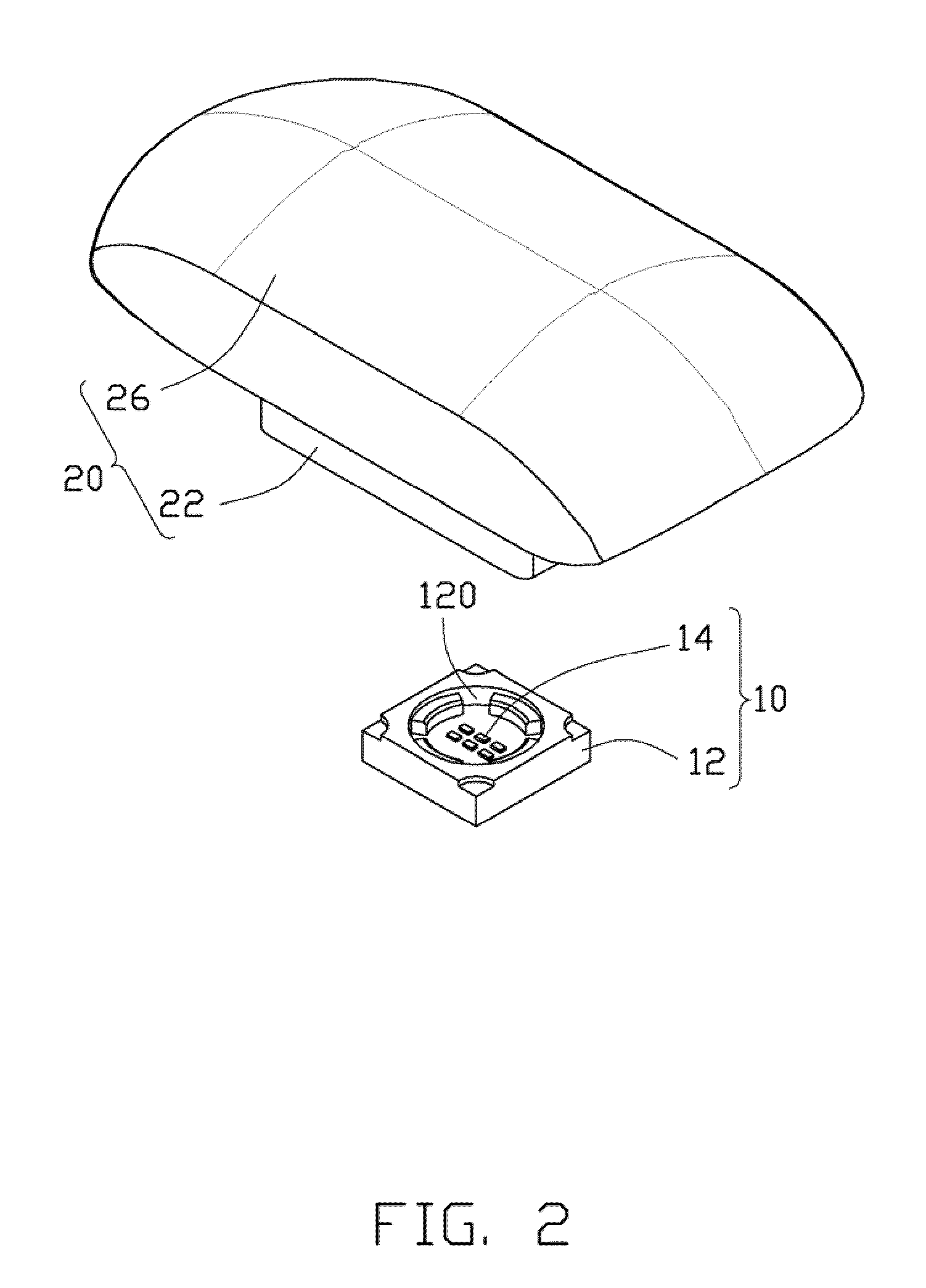
[0014]FIGS. 1 to 4 illustrate an LED module in accordance with an exemplary embodiment, which includes an LED 10 and a lens 20 covering the LED 10.

[0015]Referring to FIG. 1, a three dimensional coordinate system, with origin O and axes X, Y and Z, oriented as shown by the arrows in FIG. 1, is adopted to clearly describe the LED module. Any two of the three axes X, Y, Z are perpendicular to each other. The X-axis and the Z-axis cooperatively define a first plane XOZ, the Y-axis and the Z-axis cooperatively define a second plane YOZ, and the X-axis and the Y-axis cooperatively define a third plane XOY. The first plane XOZ and the second plane YOZ are vertical, and are perpendicularly intersected at the Z-axis. The third plane XOY is horizontal, perpendicularly intersected to the first plane XOZ at the X-axis and perpendicularly intersected to the second plane YOZ at the Y-axis.

[0016]Referring to FIGS. 2 and 4, the LED 10 includes a rectangular base 12 and a plurality of LED chips 14. ...


PUM


Abstract

An LED module includes an LED and an elongated lens. The lens includes a center axis, a concave incident face, and an opposite convex emitting face. The emitting face includes a portion with a curvature radius at any point along a first plane larger than a distance between the point and the LED, and larger than a curvature radius at a corresponding point of the incident face on the first plane. A curvature radius at any point of the portion of the emitting face along a second plane perpendicularly intersected with the first plane at the center axis is larger than a distance between the point and the LED, while smaller than a curvature radius of a corresponding point at the incident face on the second plane. A radiating angle of the LED module in the first plane is larger than that in the second plane.

Description

BACKGROUND[0001]1. Technical Field[0002]The present disclosure relates generally to LED modules, and more particularly to an LED module with an improved lens.[0003]2. Description of Related Art[0004]LED lamp, a solid-state lighting, utilizes LEDs as a source of illumination, providing advantages such as resistance to shock and nearly limitless lifetime under specific conditions. Thus, LED lamps present a cost-effective yet high quality replacement for incandescent and fluorescent lamps.[0005]Known implementations of LED modules in an LED lamp employ lenses for focusing light generated by the LEDs. However, a light pattern provided by such LED module is substantially round, which is not suitable for illuminating a certain location, such as roadway. For a roadway, it is required that the light generated by the lamp is directed along the extending direction of the roadway and altogether illuminates a road surface of the roadway. It is preferable that the light is prevented from lightin...

Claims


Application Information

Patent Timeline
Patent Type & Authority Patents(United States)
IPC IPC(8): F21V5/00
CPCF21V5/04F21V7/0091G02B19/0028G02B19/0061F21V17/06Y10S362/80F21Y2101/02F21Y2115/10
Inventor ZHANG, HAI-WEIHUANG, XING-GUI
Owner FU ZHUN PRECISION IND SHENZHEN
Why Eureka
Try Eureka