Electric actuator

a technology of actuators and actuators, applied in the direction of gearing, mechanical control devices, instruments, etc., can solve the problems of difficult to obtain the desired widthwise dimension of the guide rail, the slide block cannot be smoothly displaced along the housing in some situations, and the housing inevitably becomes large in size. , to achieve the effect of reliably and smoothly displaced

Active Publication Date: 2011-04-12
SMC CORP
View PDF15 Cites 12 Cited by
  • Summary
  • Abstract
  • Description
  • Claims
  • Application Information

AI Technical Summary

Benefits of technology

[0009]A general object of the present invention is to provide an electric actuator, in which the actuator can be successfully miniaturized while suppressing both the height and widthwise dimensions thereof, as well as to provide a displacement member that can be displaced reliably and smoothly even when an external force is applied to the displacement member.

Problems solved by technology

However, in this case, the housing inevitably becomes large in size, because the transmitting belt is arranged on the outer sides of the guide rail.
Thus, it is difficult to obtain a desired widthwise dimension of the guide rail while the widthwise dimension of the electric actuator itself is suppressed.
Therefore, for example, when an external force is applied in the moment direction with respect to the slide block, the slide block cannot be smoothly displaced along the housing in some situations.

Method used


Image

  • Electric actuator
  • Electric actuator
  • Electric actuator

Examples


Embodiment Construction

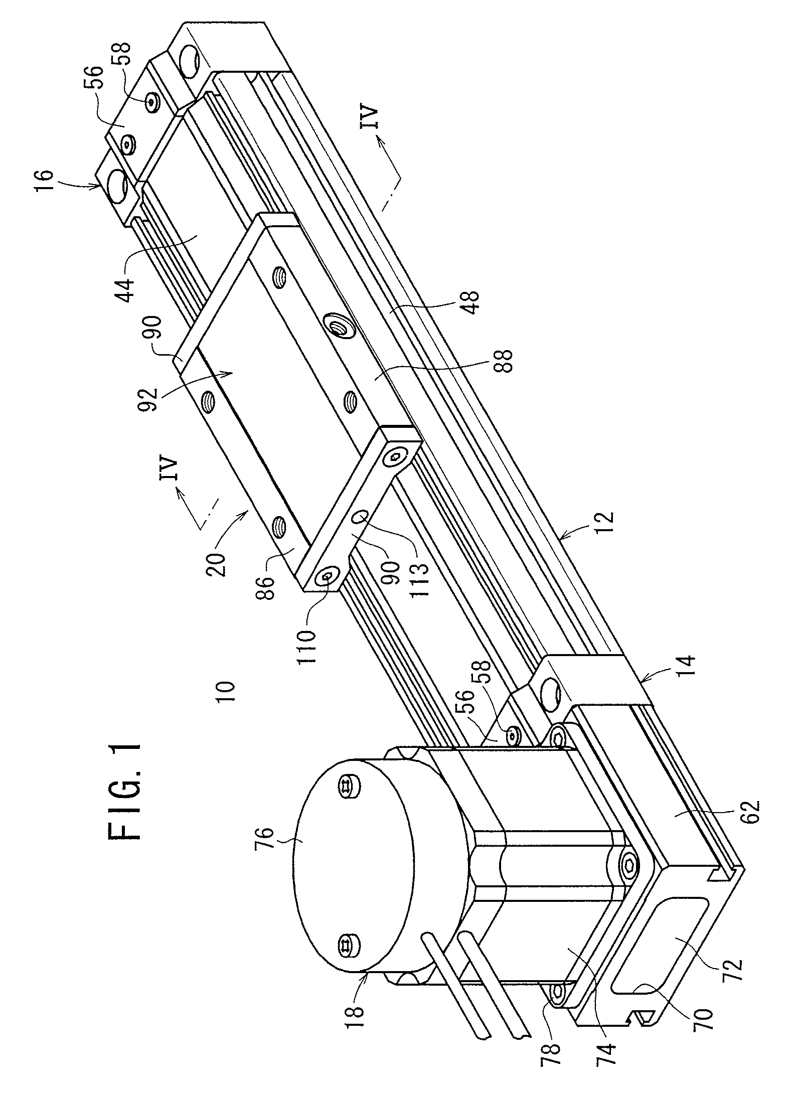
[0019]With reference to FIG. 1, reference numeral 10 indicates an electric actuator according to an embodiment of the present invention.

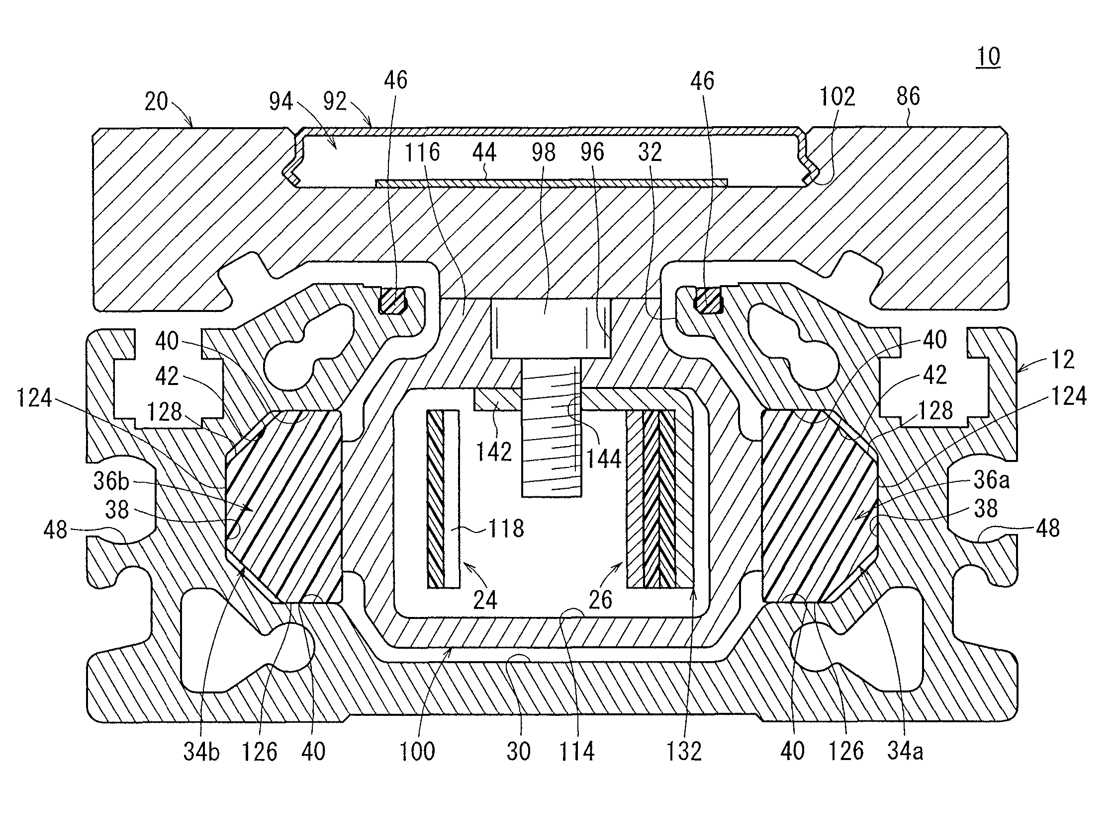
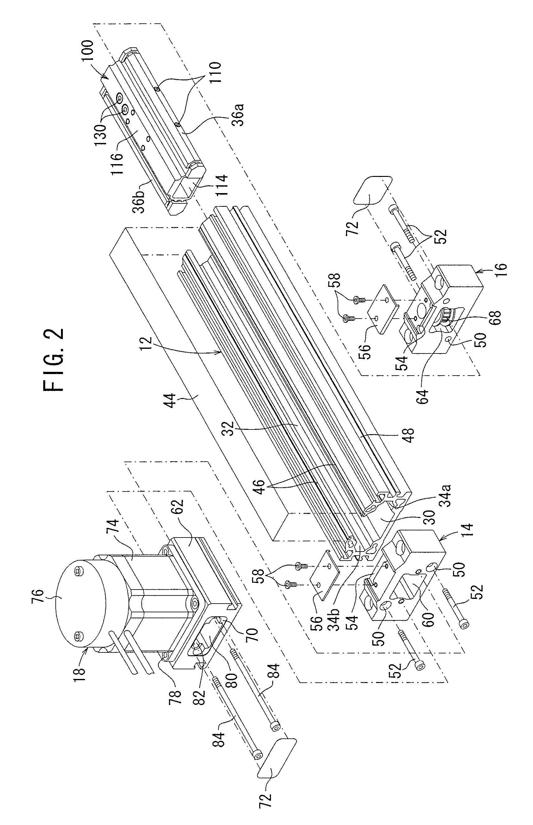
[0020]As shown in FIGS. 1 to 4, the electric actuator 10 comprises a frame 12 that is elongated in an axial direction, a pair of first and second end blocks 14, 16 connected to both end portions of the frame 12, a driving section 18 connected to the first end block 14 and which is driven in accordance with an electric signal, a slider (displacement member) 20 that transports a workpiece (not shown), and a timing belt (driving force-transmitting belt) 24, which transmits a driving force to the slider 20 through a driving pulley 22 connected to the driving section 18.

[0021]The electric actuator 10 further comprises a belt-adjusting mechanism 26, which is capable of adjusting the tensile force of the timing belt 24, along with a belt-fixing mechanism 28 (see FIG. 5), which fixes the ends of the timing belt 24 to the belt-adjusting mechanism 26.

[0022]As...


PUM


Abstract

A hollow yoke is inserted into a bore section of a frame. The yoke is connected to a slider via a slit in the frame. A timing belt is inserted into a belt hole of the yoke. Further, a pair of guide members are provided on both side surfaces of the yoke, which engage with guide grooves of the frame. The yoke is displaced along the guide grooves by the timing belt, under a driving action of a driving section. Accordingly, the slider is displaced in the axial direction along the frame.

Description

BACKGROUND OF THE INVENTION[0001]1. Field of the Invention[0002]The present invention relates to an electric actuator for moving a displacement member by transmitting a driving force of a driving section to the displacement member via a driving force-transmitting belt.[0003]2. Description of the Related Art[0004]An electric actuator, which displaces a slider in order to transport a workpiece or the like, by driving a belt by means of a rotary driving force of a rotary driving source such as a motor, has been hitherto widely used as a workpiece-transporting apparatus.[0005]In recent years, an electric actuator having a thin type of structure has been developed, in which a height dimension of the electric actuator is suppressed, taking into account demands of the installation space as well as the environment of use of the electric actuator.[0006]Such an electric actuator comprises, for example, a guide rail disposed in an axial direction along a central portion of a housing, and a gui...

Claims


Application Information

Patent Timeline
Patent Type & Authority Patents(United States)
IPC IPC(8): F16H7/18F16H27/02
CPCF16H19/06F16H2019/0686Y10T74/18648Y10T74/20354Y10T74/18848F15B15/14
Inventor IIDA, KAZUHIRO
Owner SMC CORP
Why Eureka
Try Eureka