Transformer

a transformer and layout technology, applied in the field of transformers, can solve the problems of lack of design flexibility in the layout of the transformer, and achieve the effect of increasing the layout area of the transformer

Active Publication Date: 2011-04-12
ADVANCED SEMICON ENG INC
View PDF5 Cites 14 Cited by
  • Summary
  • Abstract
  • Description
  • Claims
  • Application Information

AI Technical Summary

Benefits of technology

[0008]Accordingly, the present invention is directed to a transformer having an improved design flexibility.
[0022]Accordingly, while maintaining positions of the first outer loops and the second outer loops unchanged, the present invention is capable of adjusting positions of the first inner loops and the second inner loops for varying an overlapping area between the first inner loops and the second inner loops, so as to adjust the mutual inductance of the transformer. As such, when adjusting the mutual inductance between the first plane coil and the second plane coil, the present invention does not affect self-inductances of the first plane coil and the second plane coil, and won't increase a layout area of the transformer too much.

Problems solved by technology

Therefore, the transformer layout employing such a design lacks design flexibility.

Method used


Image

  • Transformer
  • Transformer
  • Transformer

Examples


Embodiment Construction

[0031]Reference will now be made in detail to the present preferred embodiments of the invention, examples of which are illustrated in the accompanying drawings. Wherever possible, the same reference counting numbers are used in the drawings and the description to refer to the same or like parts.

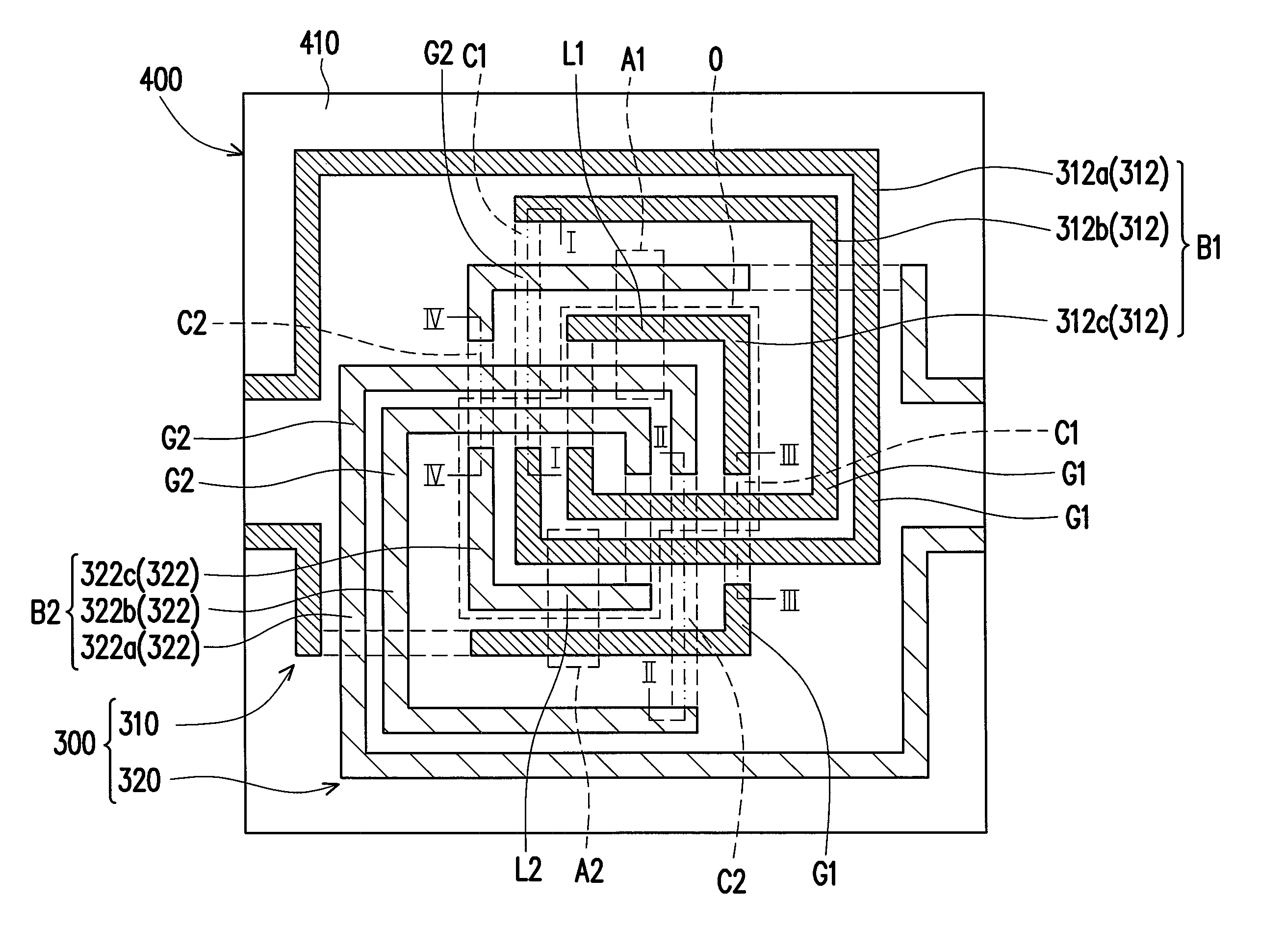
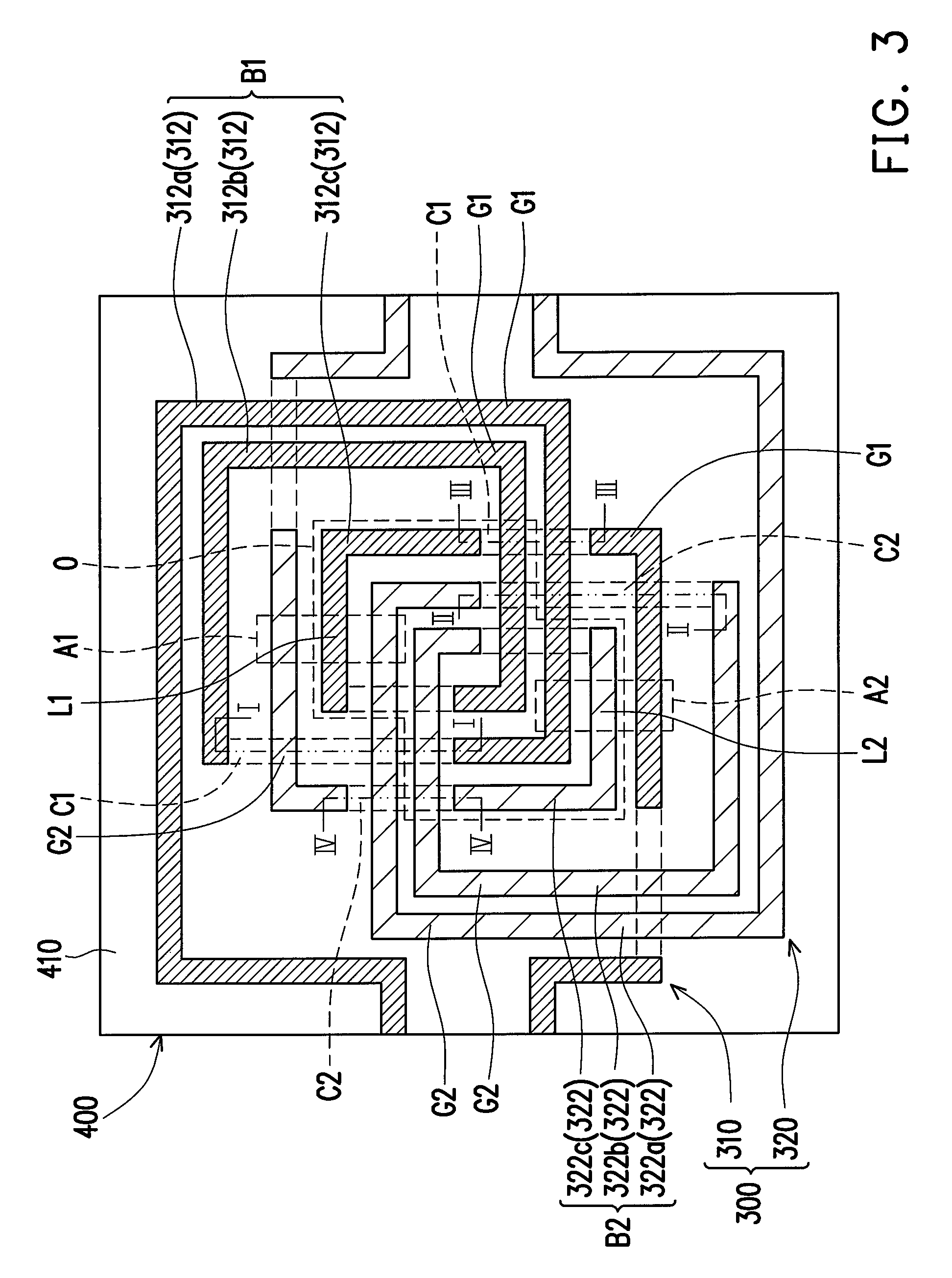
[0032]FIG. 3 illustrates a layout of a transformer according to an embodiment of the present invention. Referring to FIG. 3, it shows a transformer 300 for being configured in a wiring substrate 400. The wiring substrate 400, for example, is a printed circuit board (PCB) or an electronic package carrier. The layout of the transformer 300 includes a first plane coil 310 and a second plane coil 320, both of which are constituted by inner wirings of the wiring substrate 400. The wiring substrate 400 includes a plurality of wiring layers, a plurality of insulation layers alternately overlaying with the wiring layers, and a plurality of conductive vias passing through the insulation layers for co...


PUM

PropertyMeasurementUnit
conductiveaaaaaaaaaa
mutual inductanceaaaaaaaaaa
areaaaaaaaaaaa

Abstract

A transformer, adapted for being configured in a wiring substrate, is provided. The transformer includes a first plane coil and a second plane coil. The first plane coil includes a plurality of first loops. The second plane coil includes a plurality of second loops. A first bundle constituted by at least two adjacent first loops and a second bundle constituted by at least two adjacent second loops are stridden one over another.

Description

CROSS-REFERENCE TO RELATED APPLICATION[0001]This application claims the priority benefit of Taiwan application serial no. 97125135, filed on Jul. 3, 2008. The entirety of the above-mentioned patent application is hereby incorporated by reference herein and made a part of specification.BACKGROUND OF THE INVENTION[0002]1. Field of the Invention[0003]The present invention generally relates to a transformer, and more particularly, to transformer configured with an inner wiring inside a wiring substrate.[0004]2. Description of Related Art[0005]In a balance / unbalance filter, mutual inductance can be obtained by mutual coupling magnetic field between two inductors of a transformer, for single end transmission of differential signals. According to the trend of developing miniaturized electronic products, many electronic components have been integrated into a wiring substrate, such as passive components including capacitors, inductors, and resistors.[0006]FIG. 1 illustrates a layout of a con...

Claims


Application Information

Patent Timeline
Patent Type & Authority Patents(United States)
IPC IPC(8): H01F27/28H01F21/04H01F27/30H01F7/06
CPCH01F17/0013H01F21/04Y10T29/4902H01F2017/0073H01F2027/2819H01F2017/0046
Inventor CHEN, CHI-HANLEE, PAO-NAN
Owner ADVANCED SEMICON ENG INC
Why Eureka
Try Eureka