
Image processing method, image processing apparatus, image processing program, and image file format

a technology of image processing and image file format, applied in the field of image processing technique, can solve the problems of difficult manual operation, high-resolution image generation, complicated work, etc., and achieve the effect of high-resolution resolution conversion, high-resolution resolution conversion, and dramatic reduction of the processing amount of image processing

Active Publication Date: 2011-04-12
PANASONIC CORP
View PDF29 Cites 3 Cited by
  • Summary
  • Abstract
  • Description
  • Claims
  • Application Information

AI Technical Summary

Benefits of technology

[0019]In view of the forgoing problems, it is an object of the present invention to provide a technique for converting the resolution of an image such as improving the resolution of a moving picture, which achieves highly accurate conversion of the resolution with a small-processing amount.
[0021]With the present invention, first, the resolution conversion rules of the subject is learned by each subject characteristic from a plurality of images having different resolutions from each other. Further, the original image as a target of the resolution conversion is divided into regions based on the subject characteristics. Then, the resolution conversion rules learned regarding the corresponding subject characteristics region are applied to each region in order to convert the resolution of the original image. That is, resolution conversion of the original image is executed by applying the resolution conversion rules of each subject characteristic, so that it is possible to achieve highly accurate resolution conversion by reflecting the subject characteristics. Furthermore, the processing amount of the image processing is reduced dramatically, since the same conversion rule is applied to the regions that have the same subject characteristic regardless of their positions on the original image.
[0022]With the present invention, it is possible to achieve highly accurate resolution conversion by reflecting the subject characteristics with a small amount of image processing. The present invention therefore is effective for converting a low-resolution moving picture into a increased-resolution picture. The optical characteristics calculated from each pixel can be used as the subject characteristics, so that the characteristics can be easily applied to various scenes that change smoothly because of a complicated camerawork, a change in the distance between the camera and the subject, a change in form, rotary motion, and the like, thereby allowing generation of a high-quality moving picture. Furthermore, the present invention can be applied not only for achieving increased resolution but also for general resolution conversion. Therefore, it can be effectively utilized for generating a low-resolution image used for displaying images in low-resolution display systems such as portable telephones, for example.

Problems solved by technology

First, with the technique for generating a high-resolution image using an optical zoom as disclosed in Patent Documents 1-3, there is such a problem that the high-resolution image generated thereby is limited to a till picture. In practice, however, the resolution of a digital moving picture is lower than that of a digital still picture, so that there is a large demand for achieving increased resolution in the digital moving picture.
There are three problems as follows in the conventional techniques regarding the high resolution of moving pictures.
For that, it requires repeated actions of carrying out optical zooming by selecting minute regions within the image, which is a complicated work and it is not practical to be done manually.
Thus, the image generated thereby is no better than a series of still pictures.
Therefore, it is difficult to generate all of the high-resolution images by an interpolation technique of the still picture.
Therefore, there is not only a problem of having a heavy load of searching processing, but also having a possibility when there is a change in the distance between the subject or change in form of the subject that it becomes difficult to achieve increased resolution because the moving picture and the still picture cannot be related.

Method used


Image

  • Image processing method, image processing apparatus, image processing program, and image file format
  • Image processing method, image processing apparatus, image processing program, and image file format
  • Image processing method, image processing apparatus, image processing program, and image file format

Examples


first embodiment

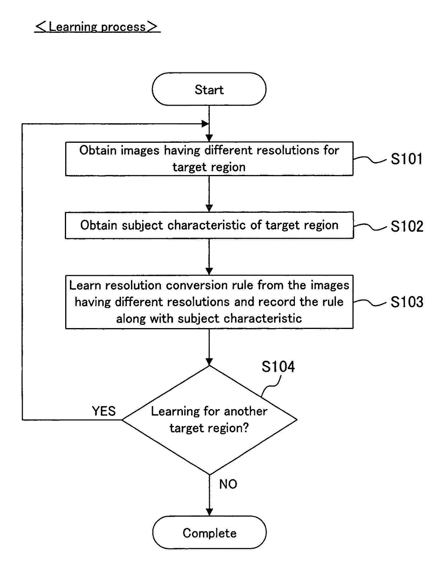
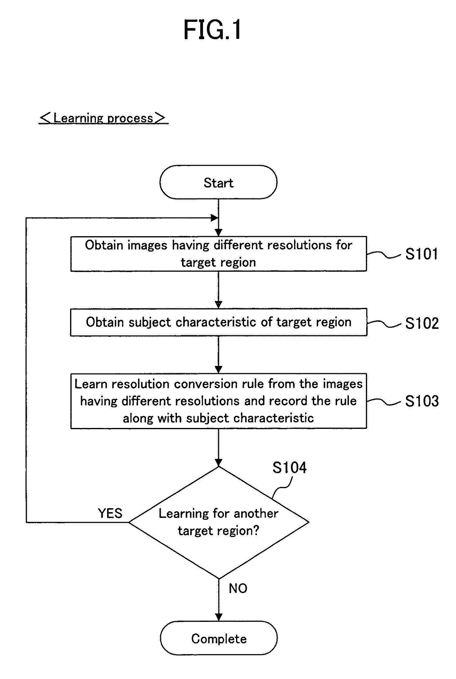
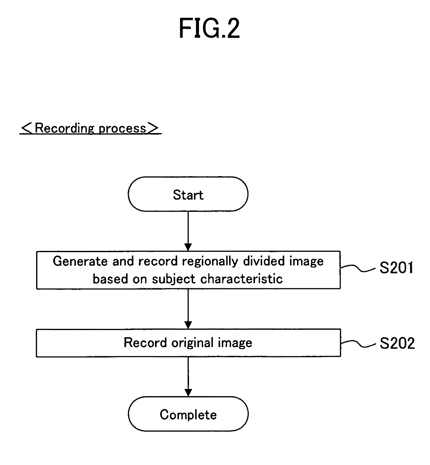
[0098]FIG. 1-FIG. 3 are flowcharts showing an image processing method according to a first embodiment of the present invention. FIG. 1 shows a learning process, in which a plurality of images of a subject having different resolutions from each other are obtained, and resolution conversion rules are learned from the plurality of images by each subject characteristic. FIG. 2 shows a recording process, in which a still picture or a moving picture of the subject is obtained as an original image, and the original image is divided into regions based on the subject characteristics. FIG. 3 shows a resolution increasing process, in which the resolution of the original image is converted by applying, to the divided regions, the resolution conversion rules learned in regards to the corresponding subject characteristics. Resolution increasing processing of the recorded original image is achieved herein in order to perform high-resolution display thereof on a display.

[0099]The subject characteri...

second embodiment

[0108]In a second embodiment of the present invention, described is a specific image processing method, having the above-described first embodiment as the base. In this embodiment, an optical zooming method is employed for obtaining the images having different resolutions. Further, the spectral information of the subject is used as the subject characteristic, and the resolution increasing parameter, i.e. the parameter indicating the corresponding relation between the texture features of the image, is used as the resolution conversion rule.

[0109]FIG. 4 is a conceptual diagram showing examples of the learning process and the recording process. As shown in FIG. 4A, when filming a moving picture of a character, a target region TA1 (face of the character in the drawing) is set in advance in the learning process, and the optical zooming is performed by directing the optical axis of a camera CA towards the target region TA1. Thereafter, as shown in FIG. 4B, it is advanced to the recording ...

third embodiment

[0133]FIG. 17 is a block diagram showing an image processing apparatus according to a third embodiment of the present invention, which illustrates an example where the present invention is applied to a video movie camera. The image processing apparatus of FIG. 17 includes: a zoom lens 301; a zoom control portion 302; a visible light / spectral pickup portion 303; a spectral image generating portion 304 for generating a spectral image as a third image that is generated from the spectral information of the subject; a visible-light image generating portion 305; a material image generating portion 306; a texture feature converting portion 307; a learned region dividing portion 308; a learned region display portion 309 as a display portion such as a display; a material-region divided image recording portion 310; a texture feature learning portion 311; a resolution increasing parameter recording portion 312; a learning button 313; a recording button 314; and an image recording portion 315.

[...


PUM


Abstract

In a learning process, first, images having different resolutions are obtained from a target region of the subject (S101). Further, the subject characteristic of the target region is obtained (S102). Then, the resolution conversion rules are learned from the images having different resolutions, and those are recorded to a storage device along with the subject characteristics (S103). When converting the resolutions, the resolution conversion rules learned for the corresponding subject characteristics are applied to each region of the original image so as to convert the resolutions of the original image.

Description

CROSS-REFERENCE TO RELATED APPLICATIONS[0001]This is a continuation of Application PCT / JP2005 / 021257, filed on Nov. 18, 2005. This non-provisional application claims priority under 35 U.S.C. §119(a) on Patent Application No. 2004-346985 filed in Japan on Nov. 30, 2004, the entire contents of which are hereby incorporated by reference.BACKGROUND OF THE INVENTION[0002]1. Technical Field[0003]The present invention relates to an image processing technique, and more particularly, to a technique for performing resolution conversion such as providing increased resolution in moving pictures.[0004]2. Background Art[0005]Due to spreading of digital video apparatus networks, it has become common to handle digital images in different standard formats in various input / output apparatuses. In particular, there are various kinds of image sizes ranging from a low resolution to an ultra-high resolution. In still pictures, it is common for an imaging element of a consumer digital still camera to have ...

Claims


Application Information

Patent Timeline
Patent Type & Authority Patents(United States)
IPC IPC(8): G06K9/40G06K9/00G06K9/32
CPCG06T3/40H04N5/2628H04N5/232H04N7/0135H04N23/951
Inventor KANAMORI, KATSUHIROMOTOMURA, HIDETOKOMOBUCHI, HIROYOSHI
Owner PANASONIC CORP
Learn More