Electric parking brake system and method for controlling the electric parking brake system

a technology of electric parking brake and electric brake system, which is applied in the direction of braking system, vehicle position/course/altitude control, instruments, etc., can solve the problem of unfavorable increase the number of times the electric motor is actuated, and achieve the effect of reducing the number

Active Publication Date: 2011-04-12
TOYOTA JIDOSHA KK
View PDF16 Cites 8 Cited by
  • Summary
  • Abstract
  • Description
  • Claims
  • Application Information

AI Technical Summary

Benefits of technology

[0007]The invention makes it possible to control a friction member pushing force to a value at which a vehicle is appropriately maintained at a standstill and to reduce the number of times an electric motor is actuated, in a control over a friction member pushing force produced in a brake in an electric parking brake system.
[0009]In the electric parking brake mechanism, when the electric motor is operated, the rotation of the rotating shaft of the electric motor is converted into the linear motion of the output member, whereby the connection portion is pulled. In the brake, the friction member is pushed against the friction face by the pushing mechanism. As a result, the brake is applied. The friction member pushing force in the brake is controlled to the target value that is set based on the moving force applied to the vehicle. The friction member pushing force is maintained by the maintaining mechanism even if electric current is not supplied to the electric motor. The tentative target value is set each time the predetermined condition is satisfied while the brake is on. When the tentative target value in the current routine is equal to or smaller than the target value in the immediately preceding routine, the target value in the current routine is set to the target value in the immediately preceding routine. When the tentative target value in the current routine is larger than the target value in the immediately preceding routine, the target value in the current routine is set to the tentative target value in the current routine. The target value may be increased but is never be decreased. Only when the tentative target value in the current routine becomes larger than the target value in the immediately preceding routine, the target value is increased. As a result, the friction force pushing force is controlled to a value at which the vehicle is appropriately maintained at a standstill. The period in which the brake is on includes at least one of the period in which the brake is being applied and the period in which the brake is on after being applied. Unlike the electric parking brake system described in JP-A-2004-142517, in the electric parking brake system according to the first aspect of the invention, the target value may be increased but is never be decreased. As a result, fluctuations in the target value are suppressed, and the number of times the electric motor is actuated is reduced. If the number of times the electric motor is actuated is reduced, wearing of a brush is suppressed, and the life of the electric motor is extended. In addition, occurrence of unnecessary slack is prevented. When the friction member pushing force is larger than the target value, the friction member pushing force is not reduced. However, when the friction member pushing force is smaller than the target value, the control for increasing the friction member pushing force may be executed. If the target value is not reduced in this control, the friction member pushing force is controlled to a value at which the vehicle is appropriately maintained at a standstill.

Problems solved by technology

This unfavorably increases the number of times the electric motor is actuated.

Method used


Image

  • Electric parking brake system and method for controlling the electric parking brake system
  • Electric parking brake system and method for controlling the electric parking brake system
  • Electric parking brake system and method for controlling the electric parking brake system

Examples


Embodiment Construction

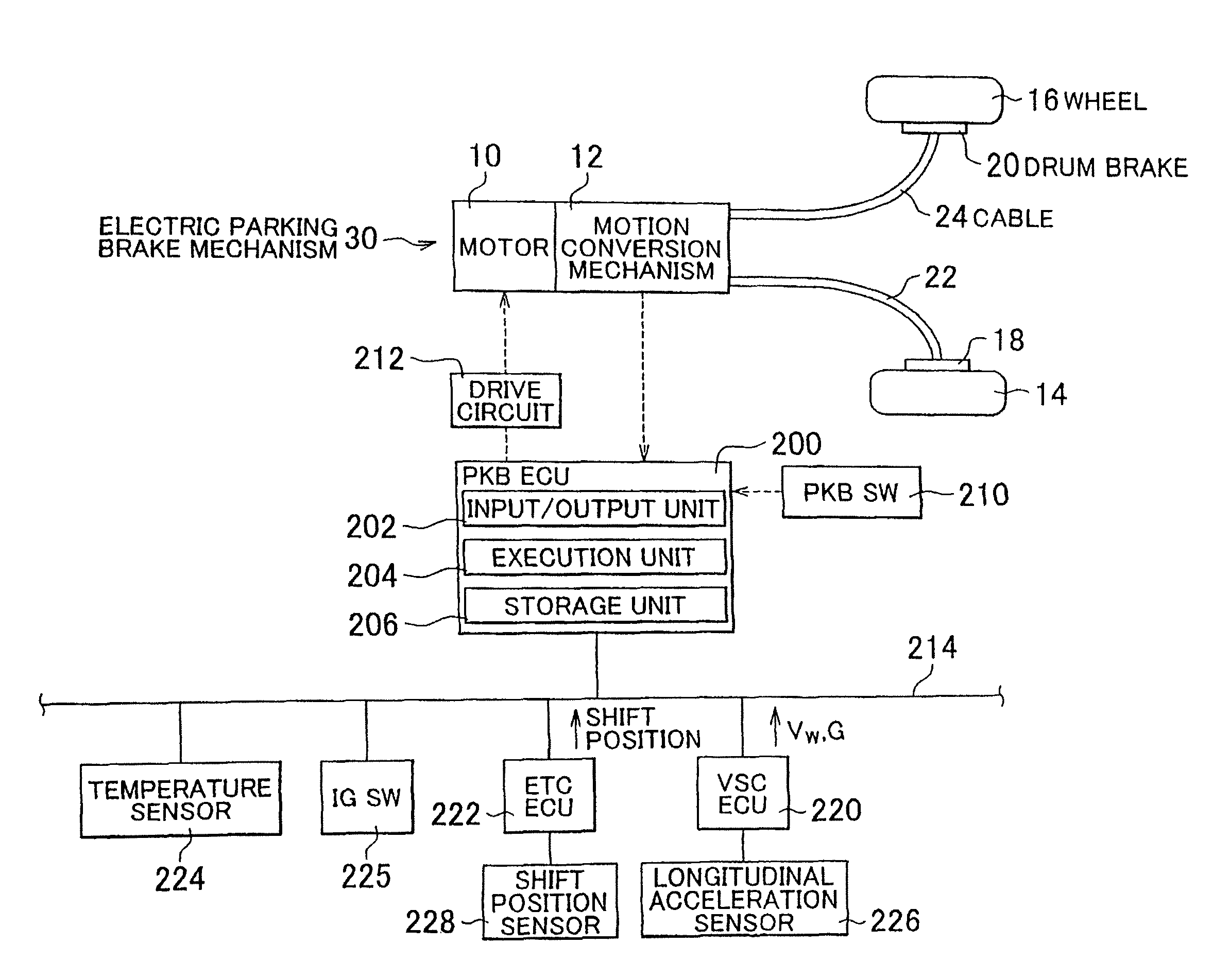
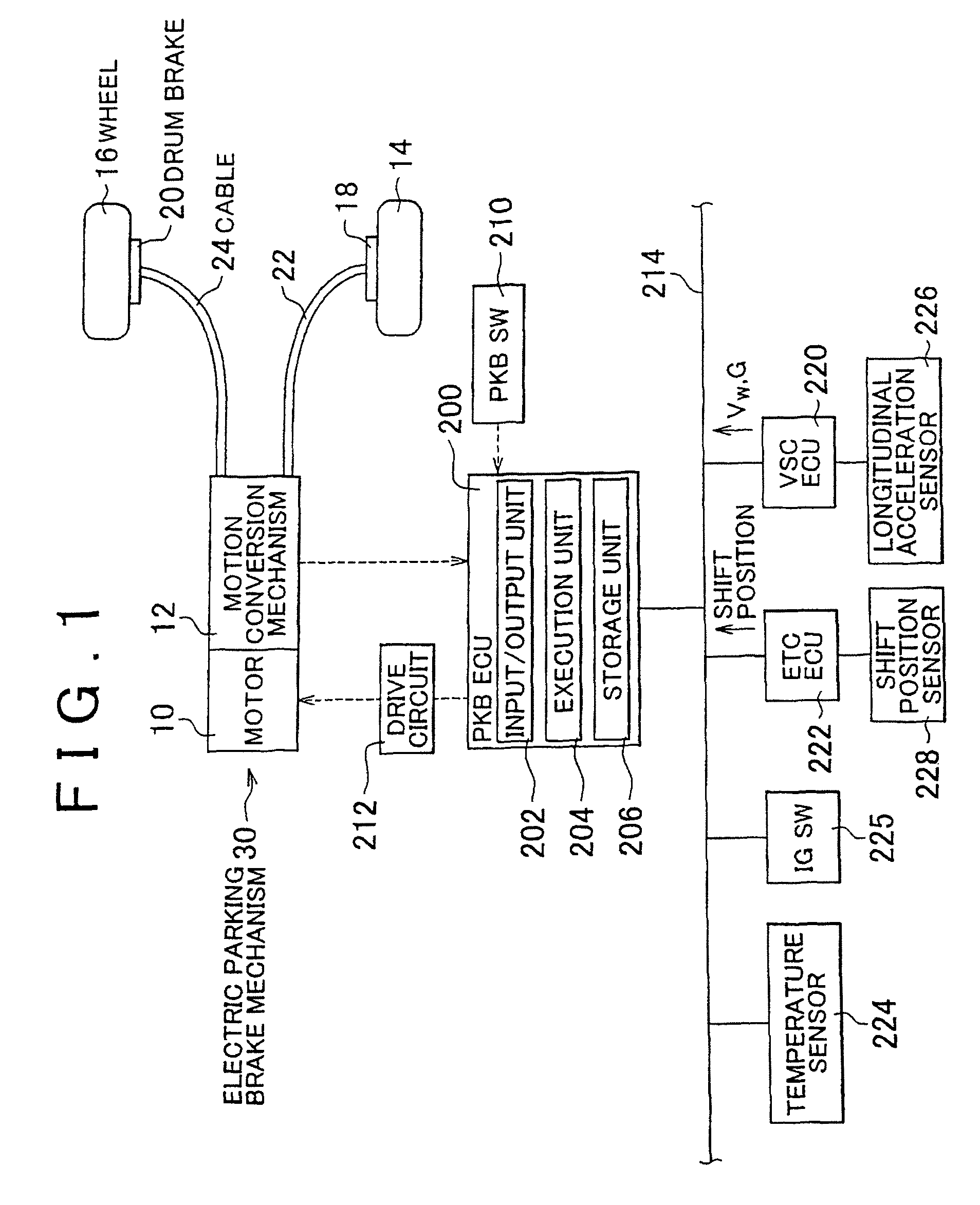
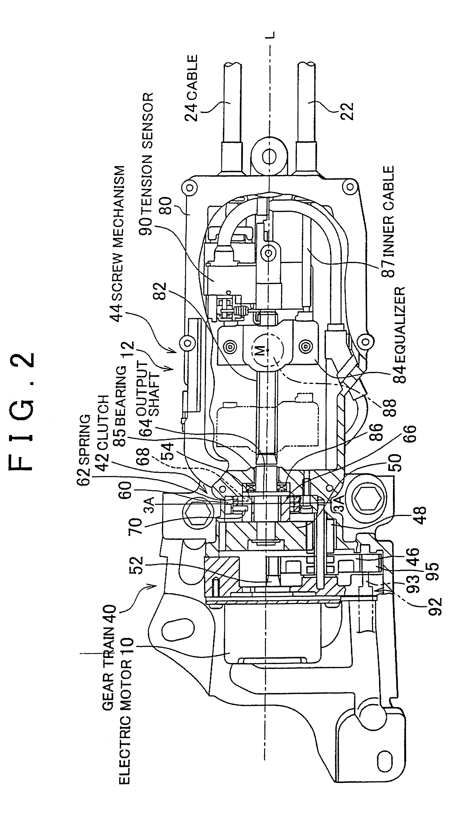
[0042]An electric parking brake system according to an embodiment of the invention will be described in detail with reference to the accompanying drawings. FIG. 1 shows an electric motor 10 and a motion conversion mechanism 12 with a clutch. The motion conversion mechanism 12 with a clutch converts the rotation of an output shaft 52 of the electric motor 10 into the liner motion of an output member, and prevents the electric motor 10 from being rotated due to a force applied to the output member. FIG. 1 also shows wheels 14 and 16, and parking brakes 18 and 20 that are provided to the wheels 14 and 16, respectively. The parking brakes 18 and 20 are connected to the motion conversion mechanism 12 via cables 22 and 24, respectively. When the cables 22 and 24 are pulled due to the operation of the electric motor 10, the parking brakes 18 and 20 are applied. According to the embodiment of the invention, the electric motor 10, the motion conversion mechanism 12 with a clutch, the cables ...


PUM


Abstract

During the standstill state maintenance control executed by an electric parking brake system, the moving force-based target tension Frefb is determined based on the inclination angle of a vehicle and the shift position each time the predetermined program is executed, and the tentative target tension Fref(n) in the current routine is set to a smaller value from among the moving force-based target tension Frefb and the maximum value Fmax. The control target tension Fref(n)* is set to a larger value from among the control target tension (the final target tension) Fref(n−1)* in the immediately preceding routine and the tentative target value Fref(n). Even if the tentative target tension Fref(n) is smaller than the control target tension Fref(n−1)*, the control target value Fref(n)* is not set to a value smaller than the control target tension Fref(n−1)*.

Description

INCORPORATION BY REFERENCE[0001]The disclosure of Japanese Patent Application No. 2006-251798 filed on Sep. 15, 2006 including the specification, drawings and abstract is incorporated herein by reference in its entirety.BACKGROUND OF THE INVENTION[0002]1. Field of the Invention[0003]The invention relates generally to an electric parking brake system and a method for controlling the electric parking brake system, and, more specifically, to a control over a force with which a pushing mechanism pushes a friction member against a friction face in the electric parking brake system.[0004]2. Description of the Related Art[0005]Japanese Patent Application Publication No. JP-2004-142517 (JP-A-2004-142517) describes a technology relating to an electric parking brake system. According to the technology, a target value of a friction member pushing force is set at predetermined time intervals and an electric motor is controlled such that the friction member pushing force approaches the target va...

Claims


Application Information

Patent Timeline
Patent Type & Authority Patents(United States)
IPC IPC(8): B60L7/00G06F17/00B60T7/12B60T13/74B60T17/22F16D65/14F16D65/28F16D66/00
CPCB60T7/122H02P3/04B60T13/746B60T2201/06
Inventor SHIRAKI, TAKAHIRO
Owner TOYOTA JIDOSHA KK
Why Eureka
Try Eureka