Offset force clamp

a clamping force and offset technology, applied in the direction of positioning apparatus, metal-working machine components, manufacturing tools, etc., can solve the problems of difficult clamping and personal injury of the machine operator, and achieve the effect of increasing or decreasing the clamping for

Inactive Publication Date: 2011-04-19
THE UNITED STATES OF AMERICA AS REPRESENTED BY THE SECRETARY OF THE NAVY
View PDF9 Cites 6 Cited by
  • Summary
  • Abstract
  • Description
  • Claims
  • Application Information

AI Technical Summary

Benefits of technology

[0004]The present invention provides an offset force clamp for holding a workpiece on a table of a cutting machine. The clamp utilizes a pair of non-symmetrical jaws that are actuated by a clamping pliers mechanism. A first jaw is affixed to one handle of the pliers and configured to releasably engage a table of a Cutting machine. A second jaw is pivotably connected to the second handle of the pliers and configured to apply a clamping force at a location remote from the first jaw. The second jaw is relatively long and narrow. The first jaw is placed into engagement with the table in a location remote from the cutting implement, the workpiece is placed on the table in a location for cutting, and the pliers' handles are moved together to cause the second jaw to hold the workpiece against the table. The typical adjusting screw of the clamping pliers is effective to increase or decrease the jaw clamping force.

Problems solved by technology

When the piece being cut is small, clamping is difficult and the clamp may be cut by the water jet along with the workpiece.
Attempting to perform a cutting operation without a mechanical clamp can result in personal injury to the machine operator.

Method used


Image

  • Offset force clamp
  • Offset force clamp
  • Offset force clamp

Examples


Embodiment Construction

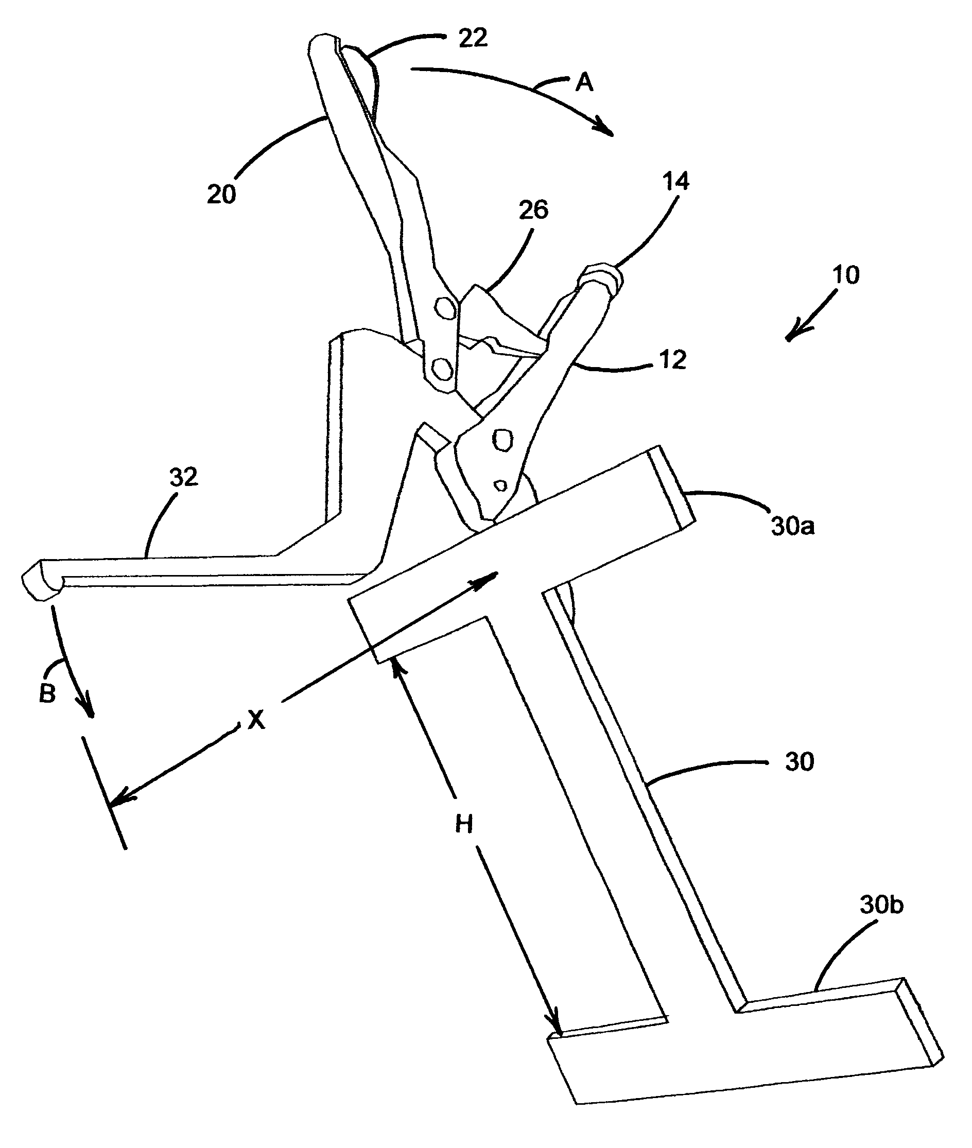
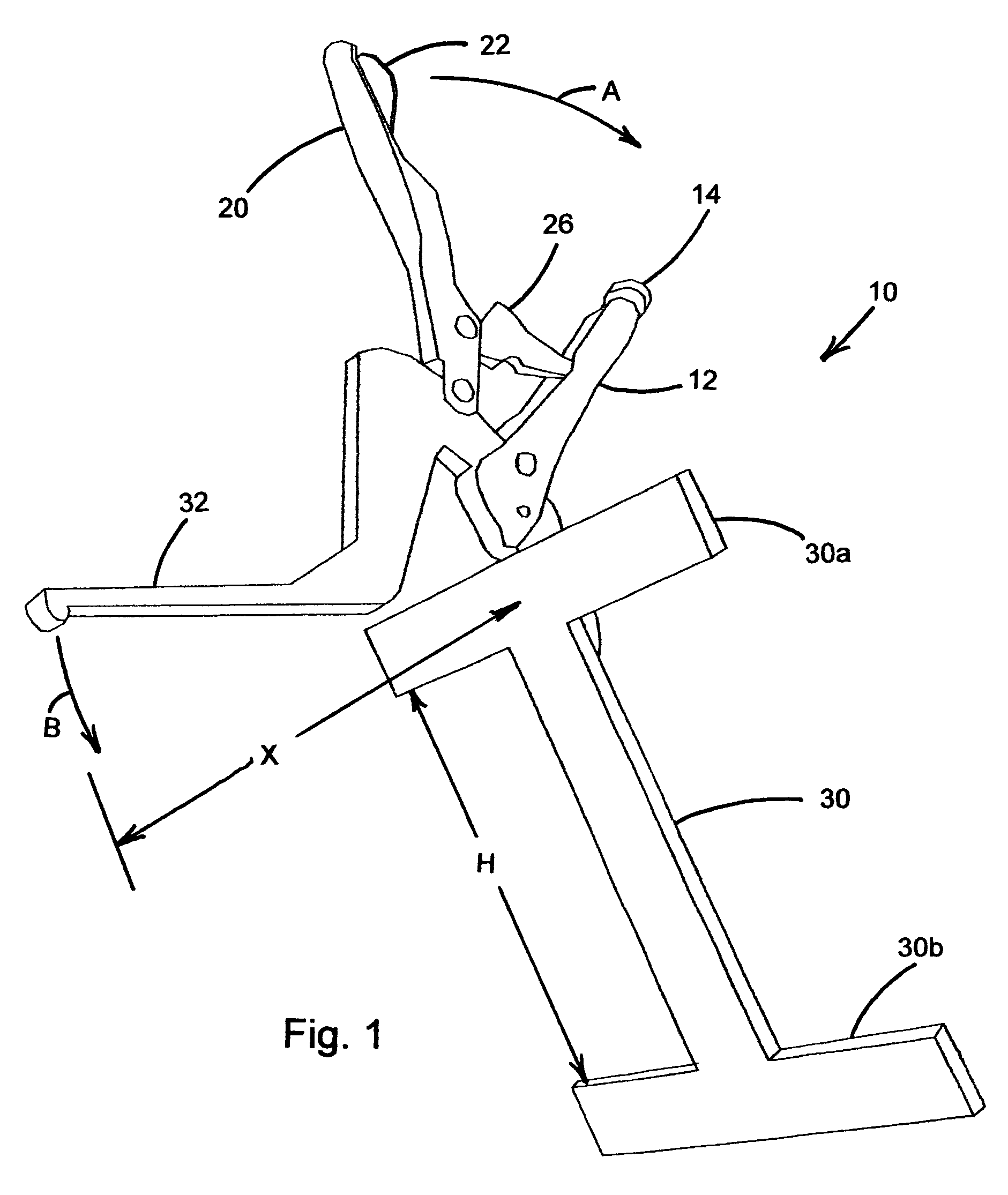
[0010]Referring to FIG. 1, an offset force clamp 10 of the invention is shown in front perspective view. Clamp 10 has a fixed handle 12 and a pivoted handle 20 that are operable to press an elongate upper jaw 32 against a workpiece as a substantially planar base jaw 30 engages a table, as will be described below. Fixed handle 12 and pivoted handle 20 are oriented in a plane that is substantially perpendicular to the plane of base jaw 30. Upper jaw 32 is oriented in a plane that is substantially parallel to handles 12 and 20 and is perpendicular to the plane of base jaw 30. The operation of clamping a workpiece involves moving pivoted handle 20 in the direction indicated by arrow A toward fixed handle 12. This movement of pivoted handle 20 daises upper jaw 32 to move in the direction indicated by arrow B. A link 26 is pivotably connected to pivoted handle 20 and engages a stop within fixed handle 12 to hold pivoted handle 20 in a locked position and apply a force for holding the jaws...


PUM


Abstract

An offset force clamp is provided for securely holding a workpiece to a table of a cutting machine. The clamp is a modified clamping pliers having a planar base jaw and an elongate upper jaw oriented perpendicular to one another. The base jaw is preferably mounted fixedly to a first handle of the clamp and the upper jaw is preferably mounted pivotably to a second handle of the clamp. The base jaw is configured to engage the table as the upper jaw applies an offset force to hold the workpiece so that the clamp is not cut during the cutting operation.

Description

FIELD OF THE INVENTION[0001]The present invention relates to the field of clamping devices, and more particularly to clamps using a pair of handles for causing a connected pair of jaws to engage a workpiece.BACKGROUND OF THE INVENTION[0002]A clamp is a tool useful either for holding two parts together during an assembly operation, e.g. gluing, or for holding one or more pieces in place on a table for machining, that is drilling, cutting, etc. A significant advance in the design and utilization of clamps was the creation of the clamping pliers, most popularly known as Vice Grip® pliers. The Vice Grip® pliers has a first handle that is rigidly connected to a first jaw and a second handle that is pivotably connected to a second jaw with an intermediate link that is pressed past a pivot center point to hold the jaws closed against the workpiece. Since the introduction of the Vice Gripe pliers, many variations of jaw configuration have been developed for specific applications. In all kno...

Claims


Application Information

Patent Timeline
Patent Type & Authority Patents(United States)
IPC IPC(8): B25B7/02B25B1/04B23Q3/02
CPCB23Q3/06B25B7/123B25B7/02B25B5/12
Inventor GALLAGHER, WILLIAM M.
Owner THE UNITED STATES OF AMERICA AS REPRESENTED BY THE SECRETARY OF THE NAVY
Why Eureka
Try Eureka