Dual axis chain support with chain pull through

a chain support and dual axis technology, applied in the field of mooring systems, can solve the problems of disadvantageous bending of the rod, not designed to minimize so-called out-of-plain bending, etc., and achieve the effect of controlling the occurrence of fatigue damag

Active Publication Date: 2011-04-19
SOFEC
View PDF13 Cites 29 Cited by
  • Summary
  • Abstract
  • Description
  • Claims
  • Application Information

AI Technical Summary

Benefits of technology

[0007]A primary object of this invention is to provide a chain support in which fatigue damage due to out-of-plane bending is reduced.
[0009]Another object of this invention is to provide a chain support that allows the upper end of the mooring line to be pulled up vertically through the assembly while at the same time allowing large vertical angle variations of the lower end of the mooring, without inducing objectionable vertical or lateral misalignment of the assembly with the mooring line.
[0010]Another object of this invention is to provide a chain support that allows adjustment of the mooring line length at any time by pulling in or letting out chain links with the capability of latching into every other chain link.
[0012]The objects identified above, along with other features and advantages result from providing a chain support with two axes of rotation and an elongated hawse pipe. The longer length of the hawse pipe ensures that small angles between the last captive chain link and the first free chain link result in a rotation of the hawse pipe about either axis of rotation.
[0013]An elongated hawse pipe is pivotally connected to a structure by a hollow trunnion block. The trunnion block is fitted with two pairs of trunnions, providing two axes of rotation that are oriented perpendicularly to each other. By routing the chain through the trunnion block, the hawse pipe remains aligned with the chain below the hawse pipe when the chain is pulled up through the connector. The second pair of trunnions is arranged below the first pair of trunnions so that the overall width of the trunnion block is comparable to that of a conventional single-axis trunnion block. This arrangement provides several advantages including a smaller footprint and interchangeability with existing single-axis chain supports.
[0015]The length of the hawse pipe is chosen such that even very small angles between the captive chain link on the chain latch and the first free chain link below the captive link generate enough torque to rotate the hawse pipe around either one of the axes. This ensures that the bending stresses in the first free link are kept at low levels and the accrual of fatigue damage can be controlled.

Problems solved by technology

Adjustment of the length of the mooring line, which is often desired before and sometimes after installation of the mooring line, disadvantageously must take place before the rod is connected, most likely on board of another vessel.
The chain stopper provides two axes of rotation, advantageously providing reduced chain wear, but it is not designed to minimize so called out-of-plain bending, which occurs when the chain is under tension and one chain link (the captive link) is fixed by the chain stopper while the adjacent link below the captive link is allowed to rotate relative to the captive link.

Method used


Image

  • Dual axis chain support with chain pull through
  • Dual axis chain support with chain pull through
  • Dual axis chain support with chain pull through

Examples


Embodiment Construction

[0022]FIG. 3 shows a single point mooring system for a vessel 1 that is moored with nine mooring lines or chains 4. A chaintable 2 is rotatably connected to the vessel 1 and to the mooring lines 4. The vessel is free to weathervane around a vertical axis 7. The upper end of each mooring line includes a section of chain 4 which is connected to the chaintable 2 using a dual-axis chain stopper 3 according to the invention. Each chainstopper 3 allows rotation of the chain around a generally horizontal first axis 5 and a generally vertical second axis 6.

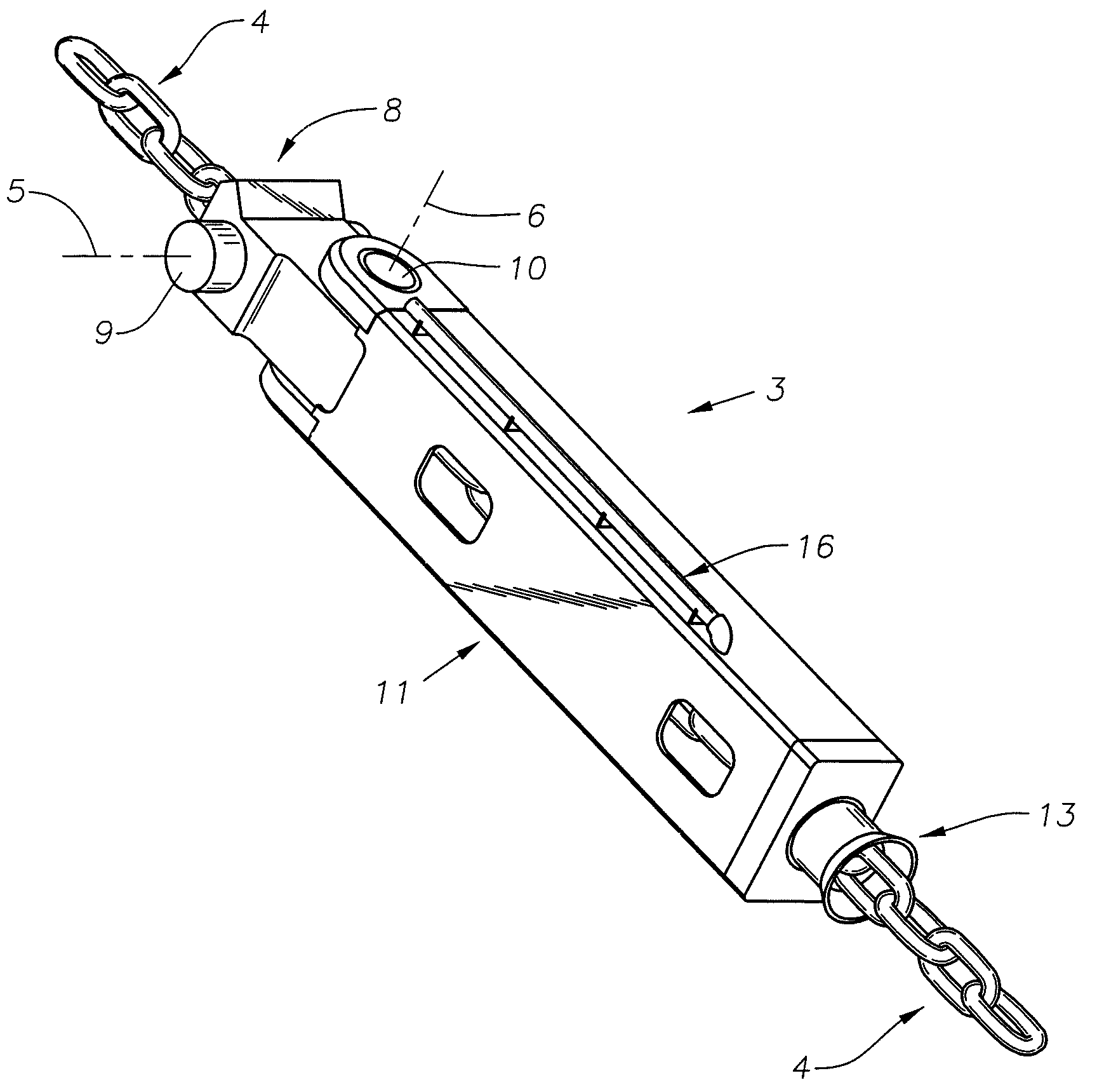
[0023]FIG. 4 shows a perspective view of the chain support 3. The mooring chain 4 is pulled through guide mouth 13 and through the interior of an elongated hollow housing 11. The chain 4 exits the chain support 3 through trunnion block 8. Since the direction of pull is often different from the orientation of the housing 11, the trunnion block 8 is fitted with a guide radius 17. (See FIG. 5) The guide radius 17 includes a groove to distrib...


PUM


Abstract

A chain support 11, hinged on two perpendicular axes 5, 6 which allows chain movement in two perpendicular planes. The chain support provides an improved arrangement to allow chain 4 to be pulled through the center of the apparatus to a desired length after which the chain is removably secured to the chain support.

Description

BACKGROUND OF THE INVENTION[0001]1. Field of the Invention[0002]This invention relates generally to mooring systems for offshore structures such as platforms and vessels and in particular, to a device which supports the mooring chain in such systems.[0003]2. Description of the Prior Art[0004]FIG. 1 illustrates a prior art mooring line connector illustrated in U.S. Pat. No. 6,663,320. This known connector allows the mooring line to rotate in two perpendicular planes relative to the offshore structure to which it is attached. The mooring line is connected using a rod and a latch mechanism. Adjustment of the length of the mooring line, which is often desired before and sometimes after installation of the mooring line, disadvantageously must take place before the rod is connected, most likely on board of another vessel.[0005]FIG. 2 illustrates a prior art mooring line connector from UK Patent Application GB2351058. The chain stopper provides two axes of rotation, advantageously providin...

Claims


Application Information

Patent Timeline
Patent Type & Authority Patents(United States)
IPC IPC(8): B63B21/00
CPCB63B21/18B63B21/04
Inventor BOATMAN, L. TERRYLINDBLADE, STEPHEN P.
Owner SOFEC
Why Eureka
Try Eureka