Frame structure

a frame structure and frame technology, applied in the field of frame structures, can solve the problems of large footprint of the device, the mat itself, and the drawback of storage of the device,

Inactive Publication Date: 2011-04-19
DDF
View PDF24 Cites 13 Cited by
  • Summary
  • Abstract
  • Description
  • Claims
  • Application Information

AI Technical Summary

Benefits of technology

[0012]In accordance with another aspect of the present invention there is provided a multi-hinge for use in a collapsible free-standing frame structure, comprising: a hinge body; N leg interconnectors for interconnecting N bowable resilient legs to said hinge body, said N leg interconnectors being pivotally mounted to said hinge body for limited pivotal motion between closed positions, in which the interconnected legs are clustered around a central longitudinal axis which extends through said hinge body, and open positions, in which the interconnected legs extend radially relative to said central axis, each of said leg interconnectors being pivotable about a leg axis extending transversely of, and being spaced from, said central axis; and a pivot stop for preventing said leg interconnectors from pivoting beyond said open positions.
[0014]In accordance with another aspect of the present invention there is provided a A collapsible free-standing frame structure kit, comprising: a) a frame structure device comprising i) N bowable resilient legs, where N is an integer greater than one; ii) a multi-hinge comprising a hinge body, N leg interconnectors for interconnecting the N bowable resilient legs to the hinge body, the N leg interconnectors being pivotally mounted to the hinge body for limited pivotal motion between closed positions, in which the interconnected legs are clustered around a central axis which extends through the hinge body, and open positions, in which the interconnected legs extend radially relative to the central axis, each of the leg interconnectors being pivotable about a leg axis extending transversely of, and being spaced from, the central axis, and a pivot stop for preventing the leg interconnectors from pivoting beyond the open positions; and b) a leg restraint for releasable attachment to distal ends of the N bowable resilient legs, the legs of the frame structure device [having] movable between a collapsed position wherein the leg interconnectors are in the closed positions, and an erected position in which the leg interconnectors can be placed in the open positions and the interconnected legs can be bowed against the pivot stop and the distal ends of the N bowed legs can be attached to the leg restraint so as to maintain the legs in the bowed position.

Problems solved by technology

In this position the device still has a footprint that is as large as the mat itself, as the bowed struts continue to apply tension to all four corners of the mat.
This large footprint has drawbacks for storage of the device.
This serves to reduce the footprint of the device, however the footprint may still be undesirably large.
Although this will reduce the footprint of the mat, the length of the unbowed struts may complicate storage.

Method used


Image

  • Frame structure
  • Frame structure
  • Frame structure

Examples


Embodiment Construction

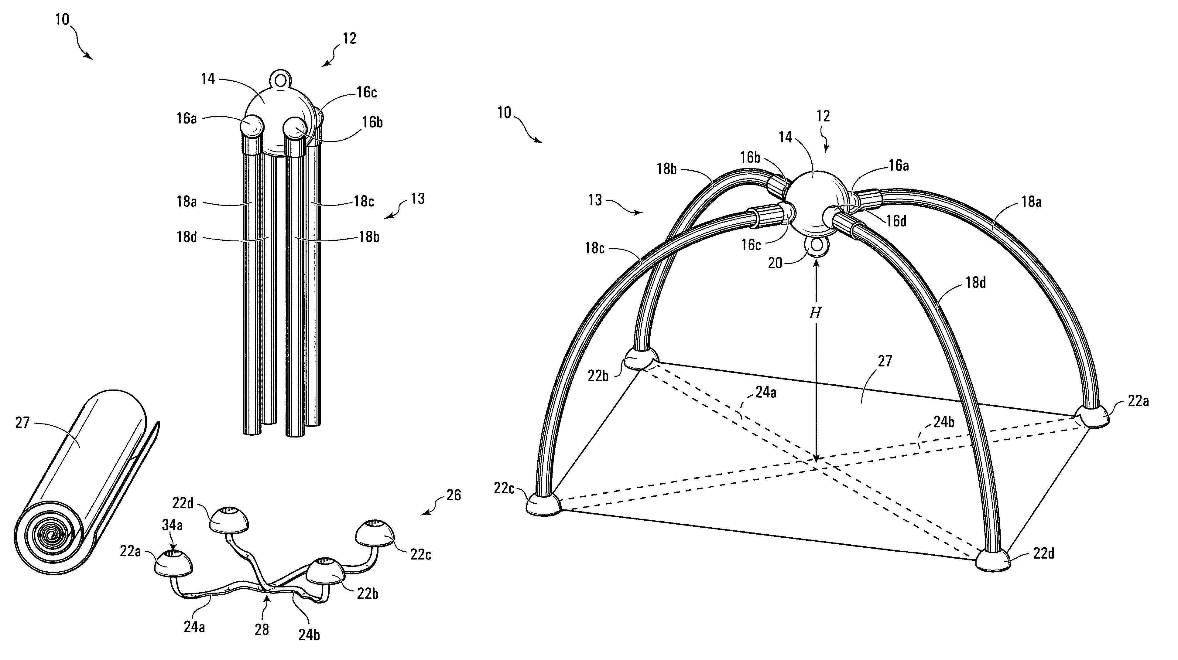
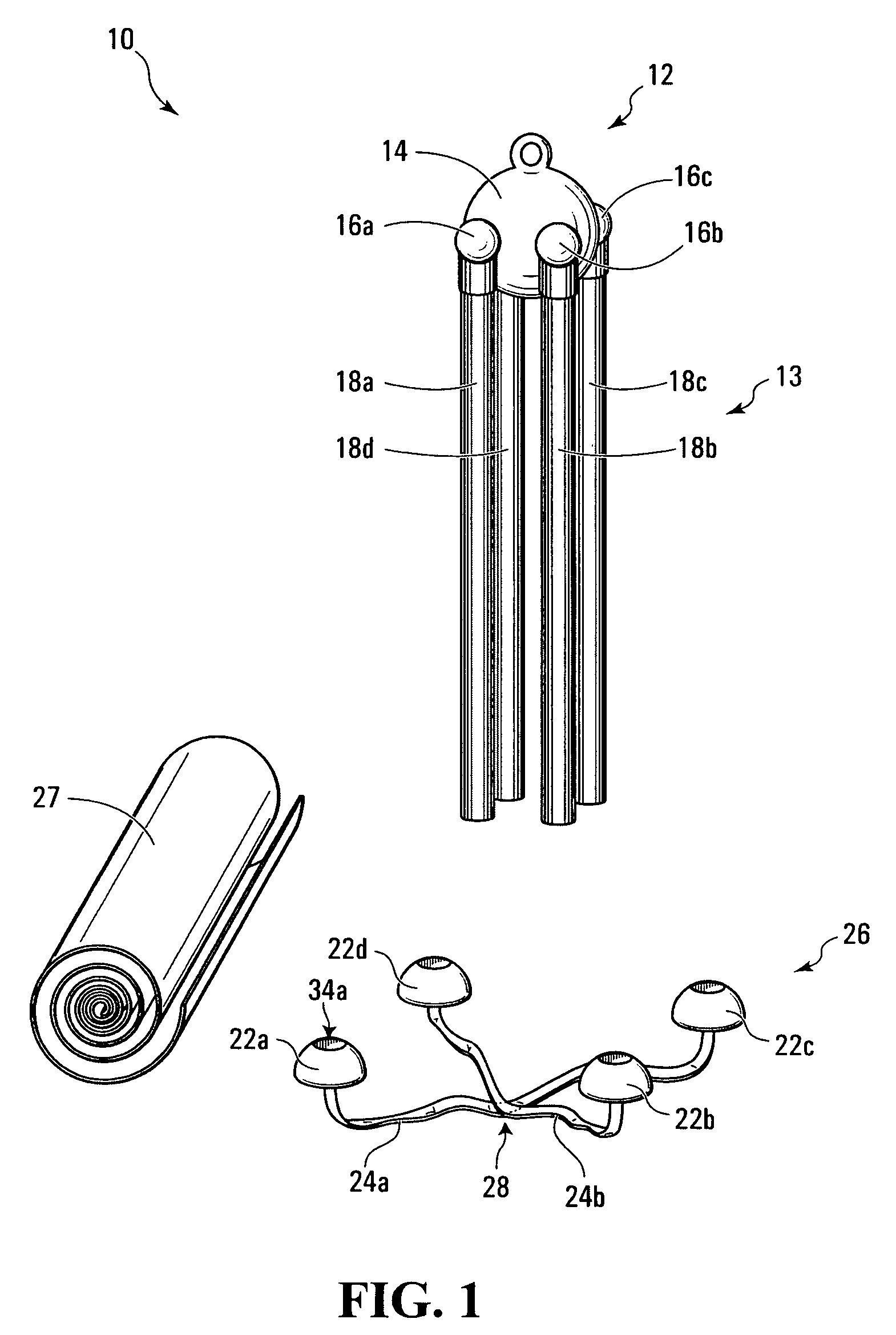
[0027]FIG. 1 illustrates a collapsible free-standing frame structure 10 and a mat 27. Frame structure 10 has a collapsed position which provides a compact profile for storage and an erected position in which the structure 10 may be used to support one or more items such as for example, infant toys. The frame structure could also be used in a wide variety of other applications such as supporting a web of material to be used for a tent or the like.

[0028]The collapsed position of frame structure 10 is shown in FIG. 1. The erected position is shown in FIGS. 7 and 8, which will be described subsequently.

[0029]As shown in FIG. 1, the frame structure 10 has two primary components, namely, a collapsible frame 13 and a leg restraint 26.

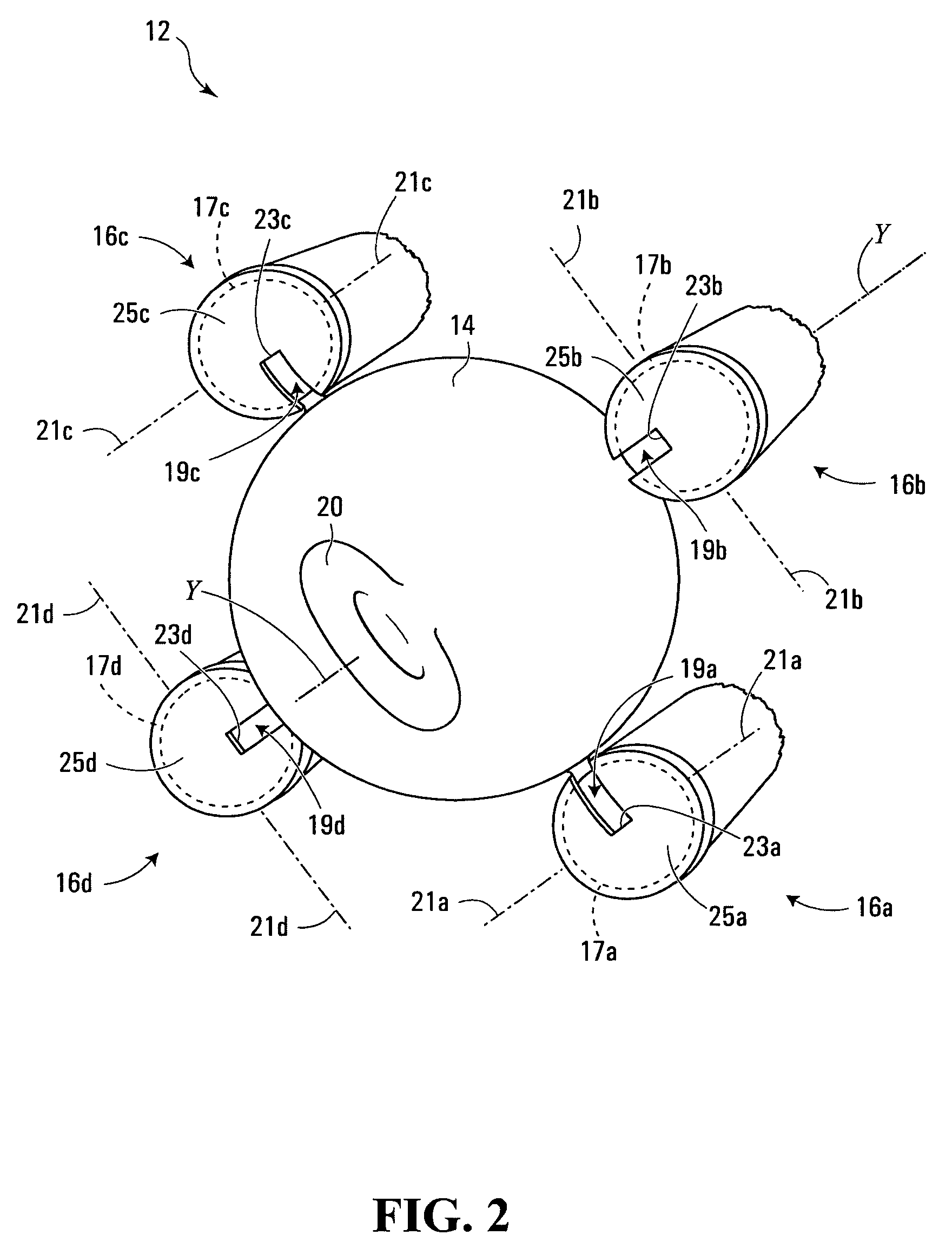
[0030]Collapsible frame 13 is formed into arches when the structure 10 is in the erected position (see FIGS. 7 and 8). Collapsible frame 13 consists of four legs 18a, 18b, 18c, and 18d (generically leg(s) 18) connected generally proximate to attachment ends th...


PUM


Abstract

A collapsible free-standing frame structure includes N bowable resilient legs, where N is an integer greater than one, a multi-hinge, and a leg restraint. The multi-hinge includes a hinge body and N leg interconnectors for interconnecting the legs to the hinge body. The leg interconnectors are pivotally mounted to the hinge body for limited pivotal motion between closed positions, in which the interconnected legs are clustered around a central axis which extends through the hinge body, and open positions, in which the interconnected legs extend radially relative to the central axis. A pivot stop prevents the leg interconnectors from pivoting beyond the open positions. To erect the frame structure, the leg interconnectors are pivoted to their open positions, the interconnected legs are bowed against the pivot stop, and the distal ends of the bowed legs are attached to a leg restraint which maintains the legs in the bowed position.

Description

FIELD OF THE INVENTION[0001]The present invention relates to frame structures, and more particularly to free-standing collapsible frame structures.BACKGROUND OF THE INVENTION[0002]Free-standing collapsible frame structures are well known. For example, various types of free-standing collapsible frame structures are known, such as those having a dome or A-frame shape and which when erected, can be used to support tents.[0003]Free standing collapsible structures may also be used to support infant's toys such as beads, rattles and mirrors within reach of an infant for purposes of promoting infant activity and improving babies' hand-eye coordination.[0004]For example, one known device suspends toys within the reach of an infant in a supine position from an overhead frame consisting of a crossed pair of arches. The device is comprised of a square cloth mat having pockets in each of its four corners suitable for receiving one end of an arch. The arches may be fiberglass rods housed within ...

Claims


Application Information

Patent Timeline
Patent Type & Authority Patents(United States)
IPC IPC(8): E04H15/40
CPCA47D15/003A47D13/066
Inventor PEREZ, SAM S.GLASER, BYRON
Owner DDF
Why Eureka
Try Eureka