Cylindrical jacket, jacket hose, suction hose, and cylindrical jacket manufacturing apparatus

a manufacturing apparatus and cylindrical technology, applied in mechanical equipment, weaving, looms, etc., can solve the problems of insufficient control of turbulence, insufficient flexibility and light weight, and inability to ensure the uniformity of the lining layer, and achieve the effect of small pressure loss

Inactive Publication Date: 2011-04-19
SAKURA GOMME KK
View PDF24 Cites 10 Cited by
  • Summary
  • Abstract
  • Description
  • Claims
  • Application Information

AI Technical Summary

Benefits of technology

[0015]The present invention has been made under the above circumstances. Accordingly, it is an object of the present invention to provide a cylindrical jacket, jacket hose and a suction hose, which can be flexible and lightweight with a small pressure loss without giving additional processing to a lining layer, and a cylindrical jacket manufacturing apparatus.
[0033]According to the cylindrical jacket of the present invention, by arranging a twill line formed by a warp woven continuously over a weft inside the cylindrical jacket, a large projected rim is formed axially by the twill line, which can match a large peripheral unevenness generated like bellows by a weft. Therefore, the cylindrical jacket can be made flexible and lightweight with a small pressure loss without additionally processing a lining layer.
[0035]According to a cylindrical jacket manufacturing apparatus of the present invention, weaving is possible while twisting a warp of a cylindrical jacket by a rotating mechanism by rotating a rotary take-in unit in synchronization with the rotation of a shuttle at an optional ratio. Therefore, a cylindrical jacket can be manufactured with a warp twisted, not straight. Particularly, as described in 13, above, a cylinder twisting mechanism having a cylinder twisting roller is provided between a ceiling and a rotary take-in unit, and a cylindrical jacket is not wrinkled even if a large twist is given, and an uniformly twisted cylindrical jacket can be obtained.

Problems solved by technology

However, if the lining layer is made thin, the texture (crossing) formed by the warp and weft becomes uneven on the inside surface of a jacket, and the uneven texture causes unevenness in the lining layer.
If the lining layer thickness is increased by providing projected rims, the flexibility and lightweight cannot be ensured.
Therefore, even if a projected rim or a groove is formed in the lining layer along the central axis of a hose, it is insufficient to control the turbulence because a large unevenness like a bellows is generated by a weft.
If the projected rim is made high or the groove is made deep by forming a thick lining layer, the flexibility and lightweight of a hose cannot be ensured.
Further, if the lining layer is given additional processing, the cost is increased.

Method used


Image

  • Cylindrical jacket, jacket hose, suction hose, and cylindrical jacket manufacturing apparatus
  • Cylindrical jacket, jacket hose, suction hose, and cylindrical jacket manufacturing apparatus
  • Cylindrical jacket, jacket hose, suction hose, and cylindrical jacket manufacturing apparatus

Examples


embodiment 1

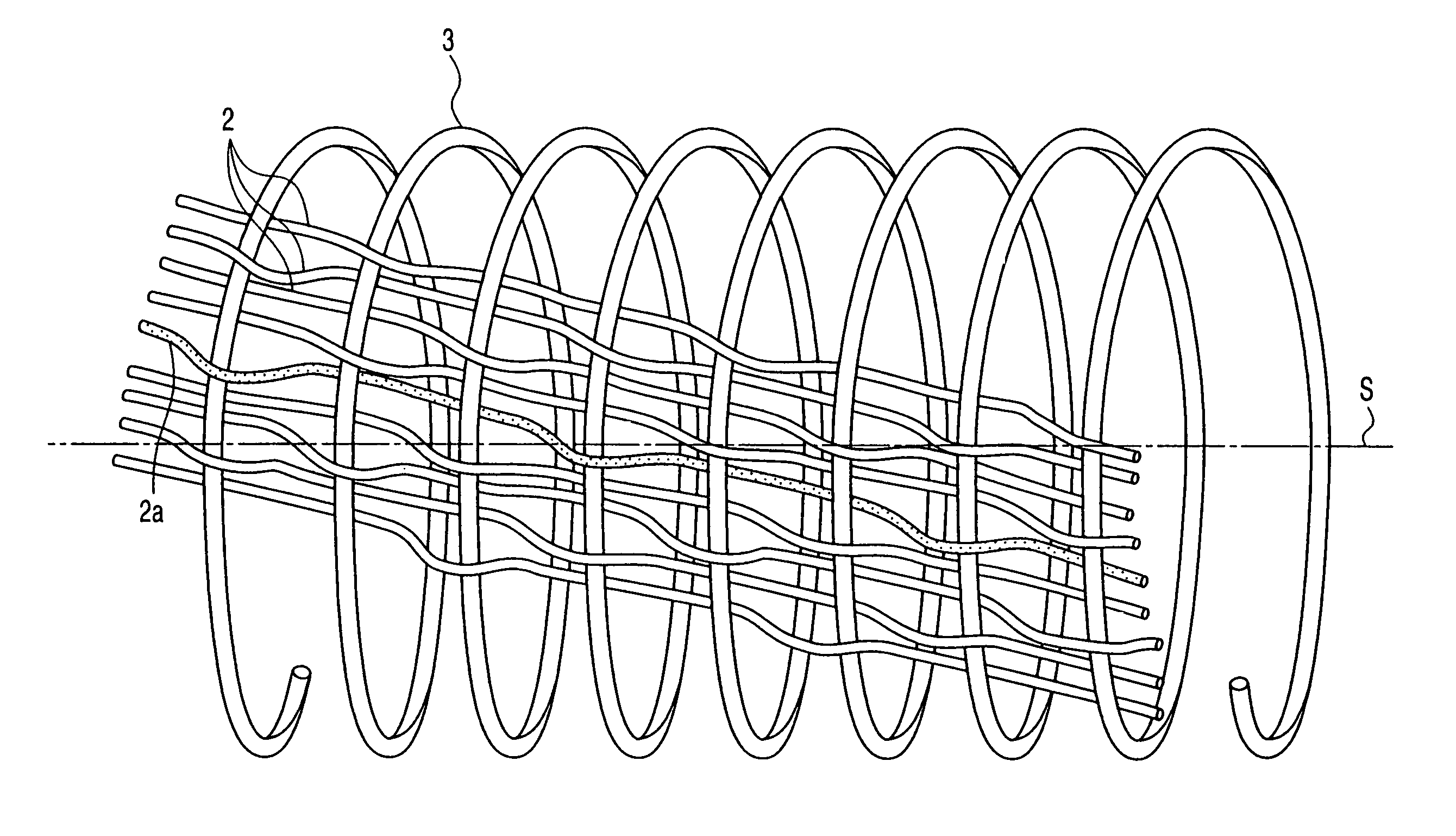
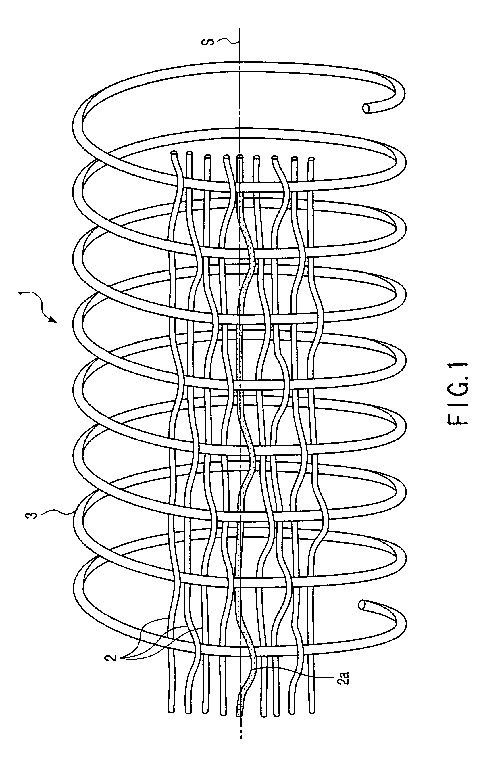
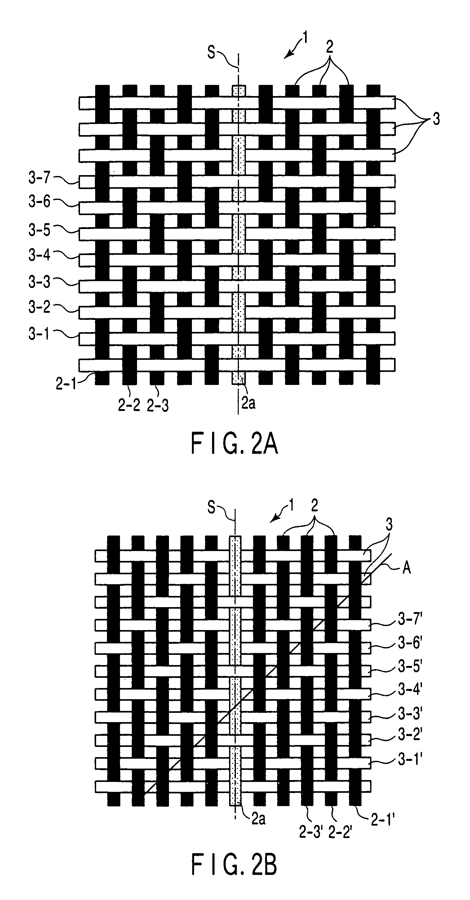
[0048]A configuration of a cylindrical jacket 1 will be explained based on FIGS. 1-4. The jacket is composed of a plurality of warp 2 made of fiber and one weft 3 made of hard steel wire. The warp 2 uses 298 white polyester threads spun into 10 / 10s and one blue shank thread 2a spun into 20 / 10s, for example. The weft 3 uses 1.8-mm-diameter galvanized hard steel, for example, and is driven to have 26 knots per 10 cm. One shank thread 2a out of the warps 2 used here is simply shown to clearly indicate the direction of the warp 2 and the direction of a twill line A formed by the warp 2 woven continuously over the weft 3 when the warp 2 and weft 3 are woven into twill, and is not directly concerned with the present invention. FIGS. 1-3 show the structures of a fabric woven by a one-shuttle cylindrical weaving machine and arranged in one line.

[0049]The cylindrical jacket 1 is remodeled to one-shuttle from the cylindrical weaving machine HM604 made by Mandal in Norway. A plurality of warp ...

embodiment 2

[0061]A cylindrical jacket manufacturing apparatus will be explained with reference to FIGS. 6-9, FIG. 6 is a front view of the manufacturing apparatus, FIG. 7 is a left side view of FIG. 6, FIG. 8 is a right side view of FIG. 6, and FIG. 9 is a plane view of a lower part fixing guide, which is one of the components of the manufacturing apparatus of FIG. 6. An upper part fixing guide described later has the same form.

[0062]As shown in FIGS. 6-8, a cylindrical weaving machine 11 is placed at a position, as it were, the second floor. The cylindrical weaving machine 11 is the Mandal HM604, for example. The cylindrical weaving machine 11 has a shuttle (not shown) to weave a weft rotating around a weaving ring 12. The shuttle feeds a weft (not shown) to the inside of the weaving ring 12, which weaves a cylindrical jacket 14 with a warp 13 fed from the outside of the cylindrical weaving machine 11.

[0063]The above manufacturing apparatus has a cylinder twisting mechanism 15, a rotary take-...


PUM


Abstract

In a cylindrical jacket woven into twill A, the direction of a twill line A formed by a warp 2 woven continuously over a weft 3 is substantially aligned with the direction of the central axis of the cylindrical jacket.

Description

CROSS-REFERENCE TO RELATED APPLICATIONS[0001]This is a Continuation Application of PCT Application No. PCT / JP2004 / 014384, filed Sep. 30, 2004, which was published under PCT Article 21(2) in Japanese.[0002]This application is based upon and claims the benefit of priority from prior Japanese Patent Application No. 2003-341962, filed Sep. 30, 2003, the entire contents of which are incorporated herein by reference.BACKGROUND OF THE INVENTION[0003]1. Field of the Invention[0004]The present invention relates to a cylindrical jacket, such as a fire hose, a shape-keep hose, a water absorption hose and an oil supply hose, a jacket hose, and a suction hose, and an apparatus for manufacturing the cylindrical jacket.[0005]2. Description of the Related Art[0006]A fire hose is generally made liquid-tight by forming a lining layer made of rubber or synthetic resin on the inside surface of a cylindrical jacket. Namely, a jacket is formed by weaving warp and weft fibers in a cylindrical form by a cy...

Claims


Application Information

Patent Timeline
Patent Type & Authority Patents(United States)
IPC IPC(8): F16L11/00D03D3/02D03D37/00
CPCD03D3/02F16L11/02D03D37/00
Inventor HORIMOTO, AKIRATOSHIRO, KENZOUKATO, KAORI
Owner SAKURA GOMME KK
Why Eureka
Try Eureka