Deflector device for partially overlapping frontal collision of motor vehicles

a technology for frontal collisions and deflectors, which is applied in the direction of steering parts, transportation and packaging, understructures, etc., can solve the problems of bumpers not being strong enough, the respective wheel penetrating into the passenger compartment, and the collision risk is increased, so as to increase the deformation distance, the effect of the deflector being shorter

Active Publication Date: 2011-04-19
MAGNA STEYR FAHRZEUGTECHN
View PDF4 Cites 40 Cited by
  • Summary
  • Abstract
  • Description
  • Claims
  • Application Information

AI Technical Summary

Benefits of technology

[0014]A further possibility is to design the forward projecting part of the deflection element as a push rod, which ends in front of or in the front cowling of the vehicle. So it reaches further forward and, in the case of a collision, will make the deflection element extend even earlier, whereby several hundredths of a second can be gained for the displacement of the deflection element, and the introduction of the impact force leading to the displacement is more favorable. So, the displacement of the deflection element is ensured even under the most unfavorable conditions.
[0017]In this case, the effect of the deflection element on the front wheel of the other vehicle involved in the collision is also increased. As a result, the deflector can be made shorter, so that in the rest position it protrudes less far out to the side. That is a significant advantage because of the restricted space available in the front part of the chassis, and in particular in the case of vehicles with wide tires. Furthermore, it permits better allowance to be made for the design of the beams for fully overlapping frontal collisions. This is so because, in the event of a fully overlapping frontal collision, they are intended to buckle or be compressed in concertina fashion to increase the deformation distance.

Problems solved by technology

There is, in particular, the risk of the respective wheel penetrating into the passenger compartment.
In addition, in cases of such collisions there is generally also a particularly dangerous phenomenon: even when there is only relatively little overlap, the front wheels on the collision side of the two vehicles become caught in one another; one wheel at least of one vehicle collides with the wheel suspension of the other and vice versa.
It can be imagined that, given the collision speeds that occur today, the bumper can never be strong enough.

Method used


Image

  • Deflector device for partially overlapping frontal collision of motor vehicles
  • Deflector device for partially overlapping frontal collision of motor vehicles
  • Deflector device for partially overlapping frontal collision of motor vehicles

Examples


Embodiment Construction

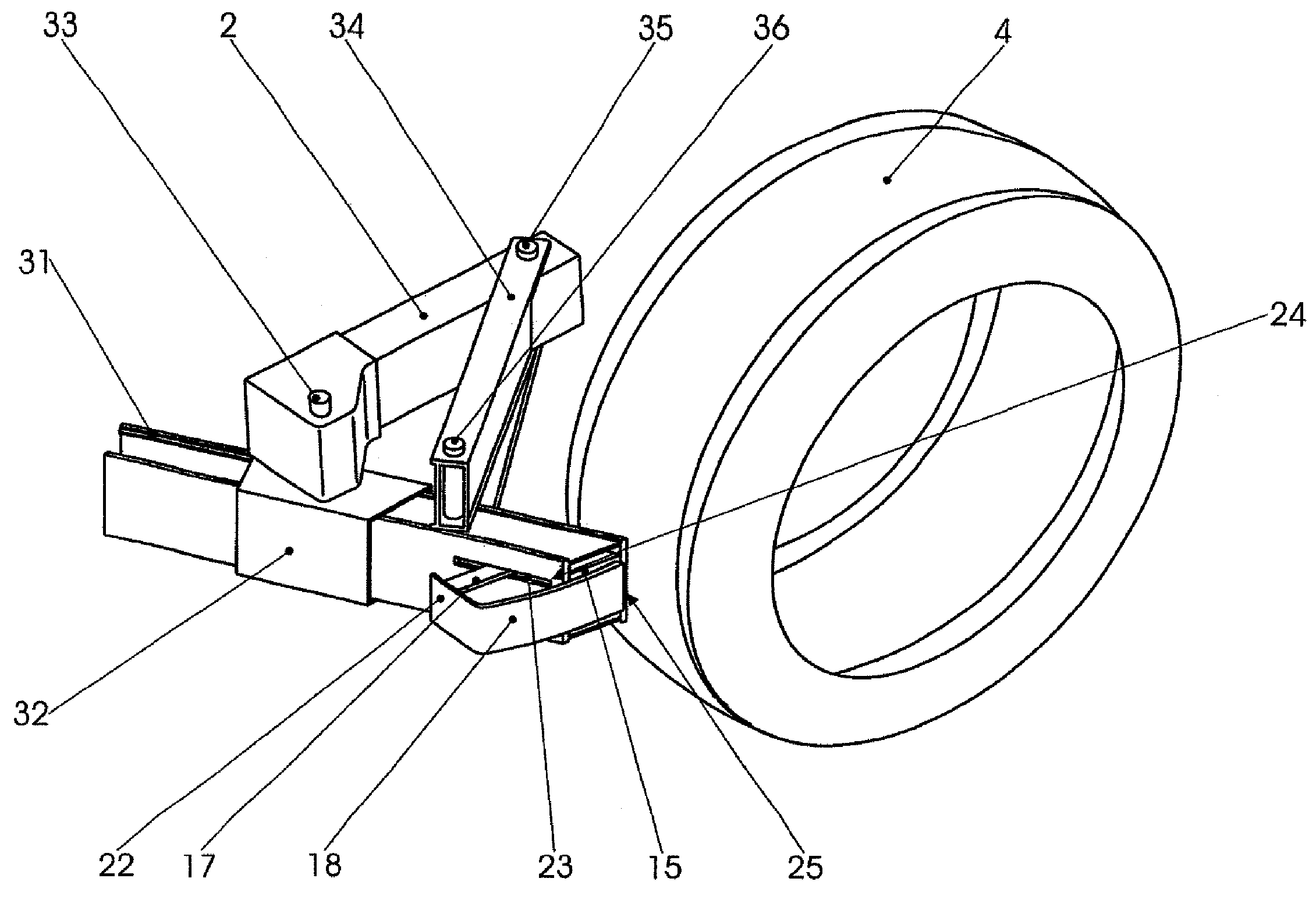
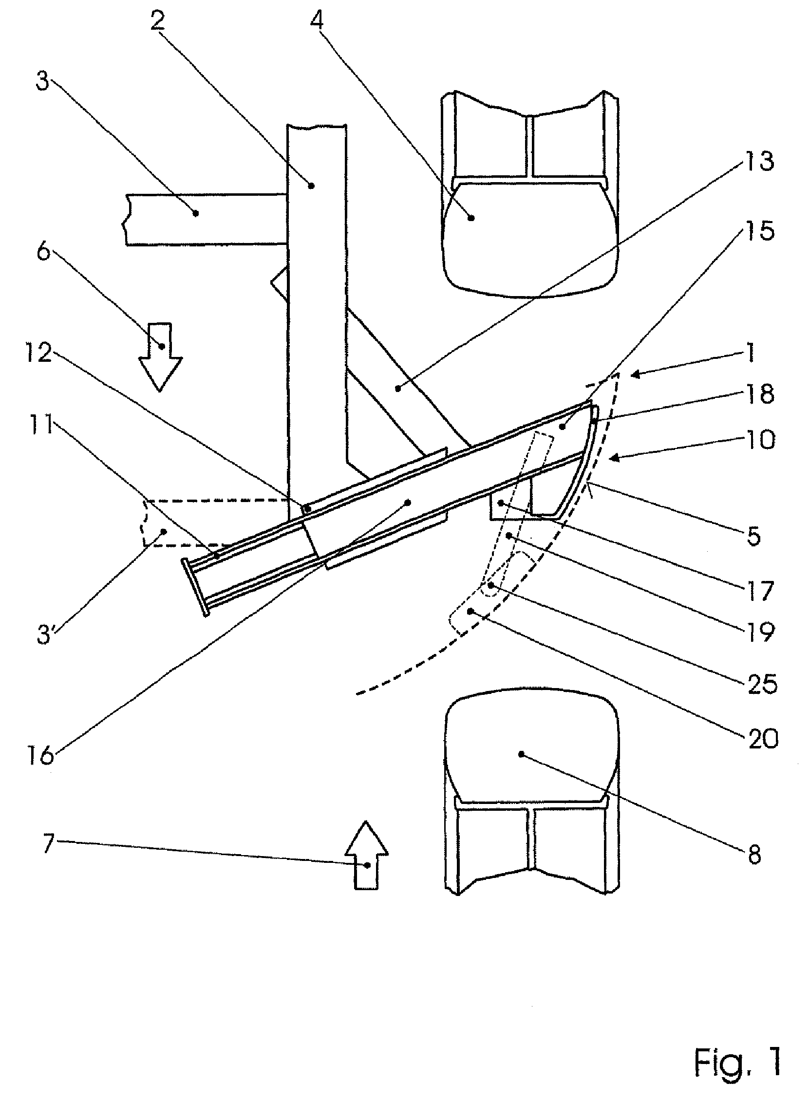
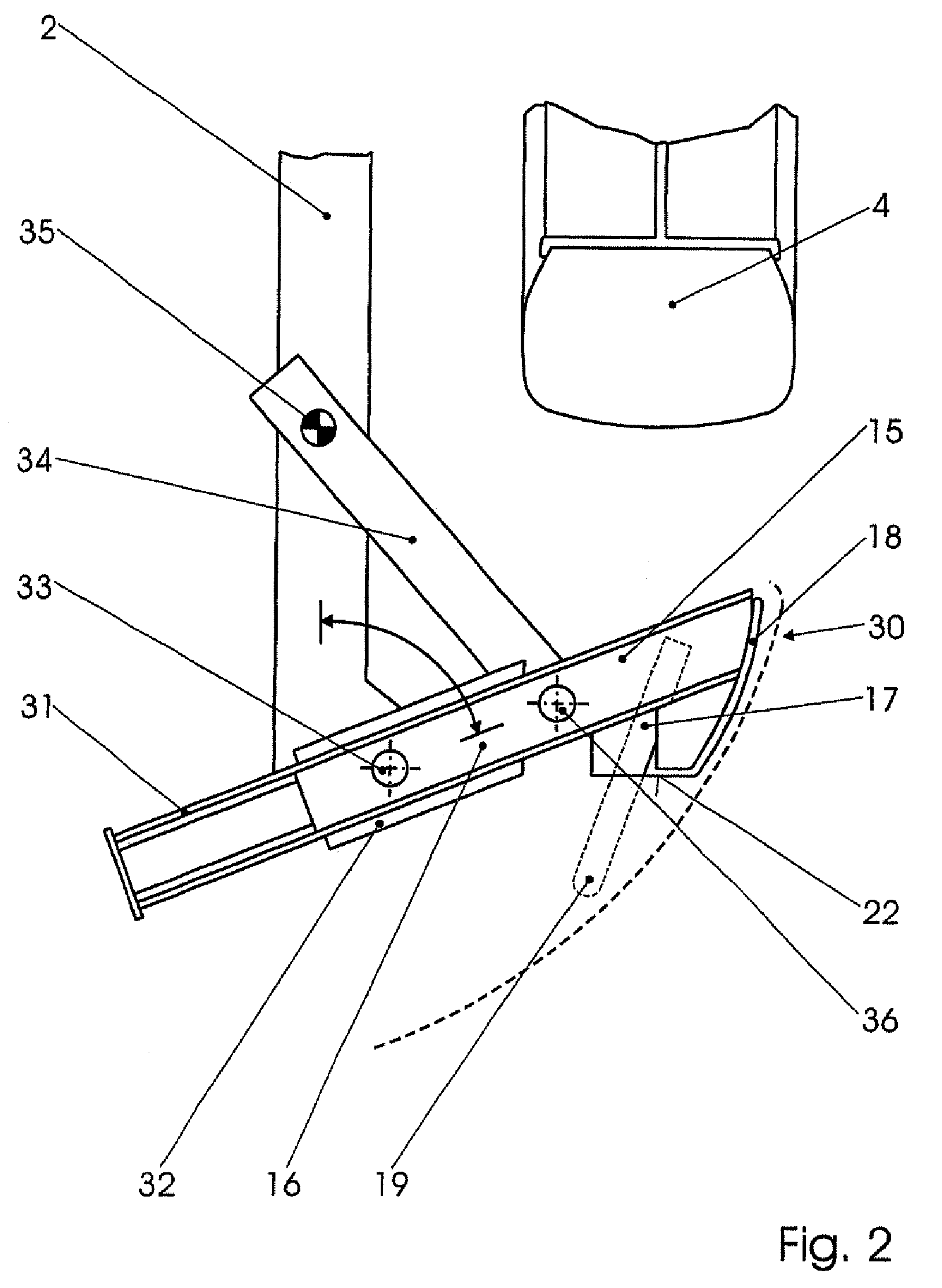
[0024]In FIG. 1, the front part of the chassis of a motor vehicle 1 is only indicated by its left-hand longitudinal beam 2 with an adjoining transverse beam 3 or 3′, by its left-hand front wheel 4 and (in dashed lines) by the contour of a front cowling 5. The right-hand side of the front part of the chassis cannot be seen, although it is generally formed in a mirror-symmetrical fashion. An arrow 6 indicates the traveling direction during forward travel. As far as another vehicle possibly involved with it in a collision is concerned, only the left-hand front wheel 8 and its direction of movement 7 are depicted. Since the vehicle 1 equipped according to the invention is to be protected in the event of an only partially overlapping frontal collision, the front wheels of the two vehicles that are respectively on the left move toward one another.

[0025]The deflector device according to the invention is designated as a whole by 10. It comprises a deflector 11, which is firmly connected to ...


PUM


Abstract

A deflector device for motor vehicles, the front part of the chassis which comprises a left-hand and right-hand longitudinal beam, arranged before a front wheel and configured by a deflector that projects from the longitudinal beam in a substantially horizontal manner and backward at an angle to protect said front wheel in the case of a collision. The deflector device prevents the vehicles from being caught and being pushed off the road in the event of a partially overlapping frontal collision. The deflector device comprises a deflection element which can be longitudinally displaced from a rest position to an operational position, said deflection element consisting of a slider guided on or in the deflector and a forward-facing shoulder.

Description

BACKGROUND OF THE INVENTION[0001]The invention relates to a deflector device for partially overlapping frontal collision of motor vehicles, the front part of the chassis of which comprises beams, which deflector device is arranged in front of a front wheel and is formed by a deflector that is connected to a beam and projects in a substantially horizontal manner and backward at an angle to protect said front wheel in the case of a collision. A partially overlapping frontal collision is to be understood as meaning a frontal collision in which the colliding vehicles are moving toward each other with substantially parallel but laterally offset directional vectors. The collision zone is consequently only a lateral part of the front part of the chassis. The beam is generally a longitudinal beam, either of the vehicle frame or of the vehicle body or of an auxiliary frame, but it could also be a transverse beam.[0002]The lateral part of the front part of the chassis of vehicles is usually l...

Claims


Application Information

Patent Timeline
Patent Type & Authority Patents(United States)
IPC IPC(8): B62D7/22
CPCB60R19/54B62D21/152B60R2021/0023B60R2019/007
Inventor AUER, THOMASSCHIMPL, WOLFGANGORNIG, ADOLF
Owner MAGNA STEYR FAHRZEUGTECHN
Why Eureka
Try Eureka