
Electrical connector

a technology of electrical connectors and connectors, applied in the direction of electrical apparatus, connection, coupling device connection, etc., can solve the problems of simplifying the internal structure of electronic products and the design of printed circuit boards, and achieve the effect of simplifying design and manufactur

Inactive Publication Date: 2011-04-19
CHANG NAI CHIEN
View PDF25 Cites 8 Cited by
  • Summary
  • Abstract
  • Description
  • Claims
  • Application Information

AI Technical Summary

Benefits of technology

"The present invention is about creating a microprocessor in an electrical connector to simplify the design and manufacture of an electronic device's internal control printed circuit board. The invention provides an electrical connector with a housing, seat body, terminal group, printed circuit board, and cover. The terminal group passes through the seat body and is connected to the printed circuit board, which in turn is connected to the electronic device's main board. The cover is placed in the housing's opening and connects to the main board. The invention simplifies the process of connecting electronic devices to external control circuits."

Problems solved by technology

Because the forgoing electrical connectors are used for simplifying external wire rod twisting of electronic products, solving information transmission rate and capable of receiving multiple data lines, but provides no suggestion of how to simplify internal structure of the electronic product and the design of the printed circuit board.

Method used


Image

  • Electrical connector
  • Electrical connector
  • Electrical connector

Examples


Embodiment Construction

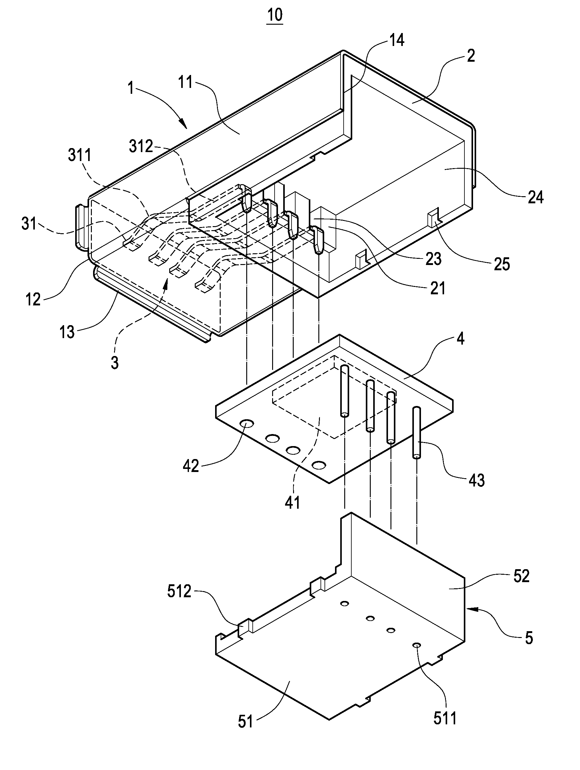
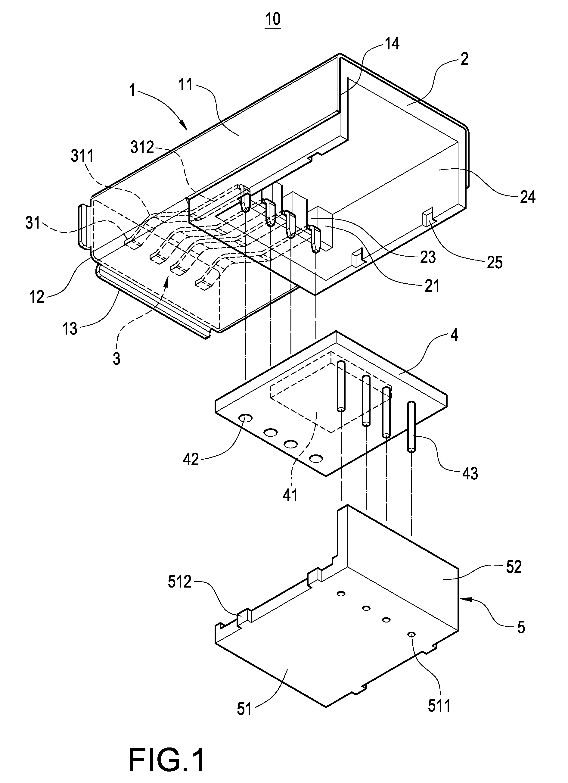
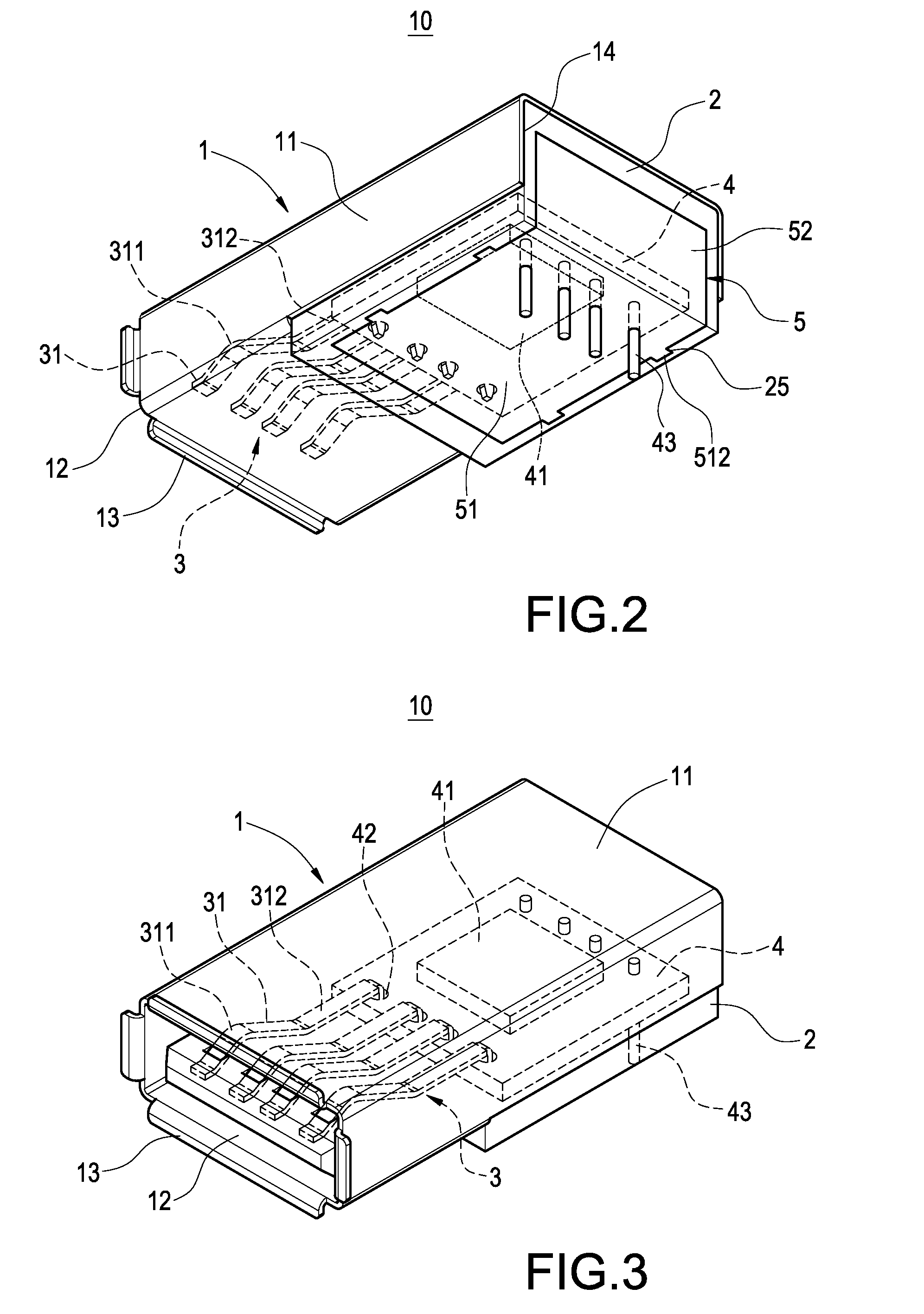
[0016]FIG. 1 is a schematic, exploded view of an electrical connector of one embodiment of the present invention. FIG. 2 is a bottom, assembled view of the electrical connector of the present invention. FIG. 3 is an assembled view of the electrical connector of the present invention, but viewed from another aspect. FIG. 4 is a side cross sectional view of the electrical connector of the present invention. Referring to FIGS. 1 to 4, the electrical connector 10 of the present invention includes a housing 1, a seat body 2, a terminal group 3, a printed circuit board 4 and a cover 5.

[0017]The housing 1 is a hollow body 11 made of metal. The hollow body 11 has a receptacle 12 at a front end. A periphery of the receptacle 12 has a plurality of arc-shaped baffle plates 13. The hollow body 11 has an opening 14 at a rear end, communicating the rear end with a bottom portion of the hollow body 11.

[0018]The seat body 2 is made of plastic and is disposed in the housing 1. The seat body 2 has a ...


PUM


Abstract

An electrical connector includes a housing, a seat body, a terminal group, a printed circuit board, and a cover. The housing has a hollow body. The seat body is disposed in the housing. The terminal group is disposed on the seat body. An end of the terminal group electrically connects with the printed circuit board. The printed circuit board electrically connects with a microprocessor. The cover covers a bottom portion of the seat body. Pins of the printed circuit board passes through the cover and electrically connects with a main board of an electronic device, making the microprocessor able to calculate or control the electronic device to execute different functions and operations.

Description

BACKGROUND[0001]1. Field of the Invention[0002]The present invention relates to an electrical connector, and more particularly, to an electrical connector with control and calculation functions.[0003]2. Description of the Related Art[0004]Electrical connectors refer to all the connecting elements and its accessories applied to electronic products and power supplies. For example, electrical connectors are required between computers and its periphery equipments such as mouse, display, keyboard, printer, and so on. Furthermore, electrical connectors are also required for transforming electric signals between different modules of electronic devices, such as IC connector, board edge connector, and so on. Thus, electrical connectors are most important accessories for electrical products.[0005]Recently, with developments of science and technology, many kinds of new electrical connectors are manufactured, such as USB, HDMI, Displayport, eSATA, SATA. In one aspect, some of the electrical con...

Claims


Application Information

Patent Timeline
Patent Type & Authority Patents(United States)
IPC IPC(8): H01R13/66
CPCH01R13/6658H01R29/00H01R12/712H01R13/6581H01R2201/06
Inventor CHANG, NAI-CHIEN
Owner CHANG NAI CHIEN
Learn More