Electrical connector element

a technology of electrical connector elements and connector elements, which is applied in the direction of fixed connections, coupling device connections, printed circuit non-printed electric components association, etc., can solve the problem of reducing the size of electrical connector elements to a limit, and achieve compact structure of electrical connector elements, adequate protection against flashover risk, and prevent flashover

Inactive Publication Date: 2011-04-19
SIEMENS AG
View PDF37 Cites 11 Cited by
  • Summary
  • Abstract
  • Description
  • Claims
  • Application Information

AI Technical Summary

Benefits of technology

[0014]An object of the present invention is to insulate the individual connector pins from one another to prevent flashover between them. In particular it should be possible to dispose the connector pins of the electrical connector element closer to one another, thereby allowing a more compact structure of the electrical connector element than is the case with conventional connector elements or where the described safe distances are predetermined. Despite the shorter distance between the connector pins, adequate protection against the risk of flashover between adjacent connector pins should however be ensured.

Problems solved by technology

However the reduction in the size of electrical connector elements reaches a limit due to the safe distance required between the individual connector pins.

Method used


Image

  • Electrical connector element
  • Electrical connector element
  • Electrical connector element

Examples


Embodiment Construction

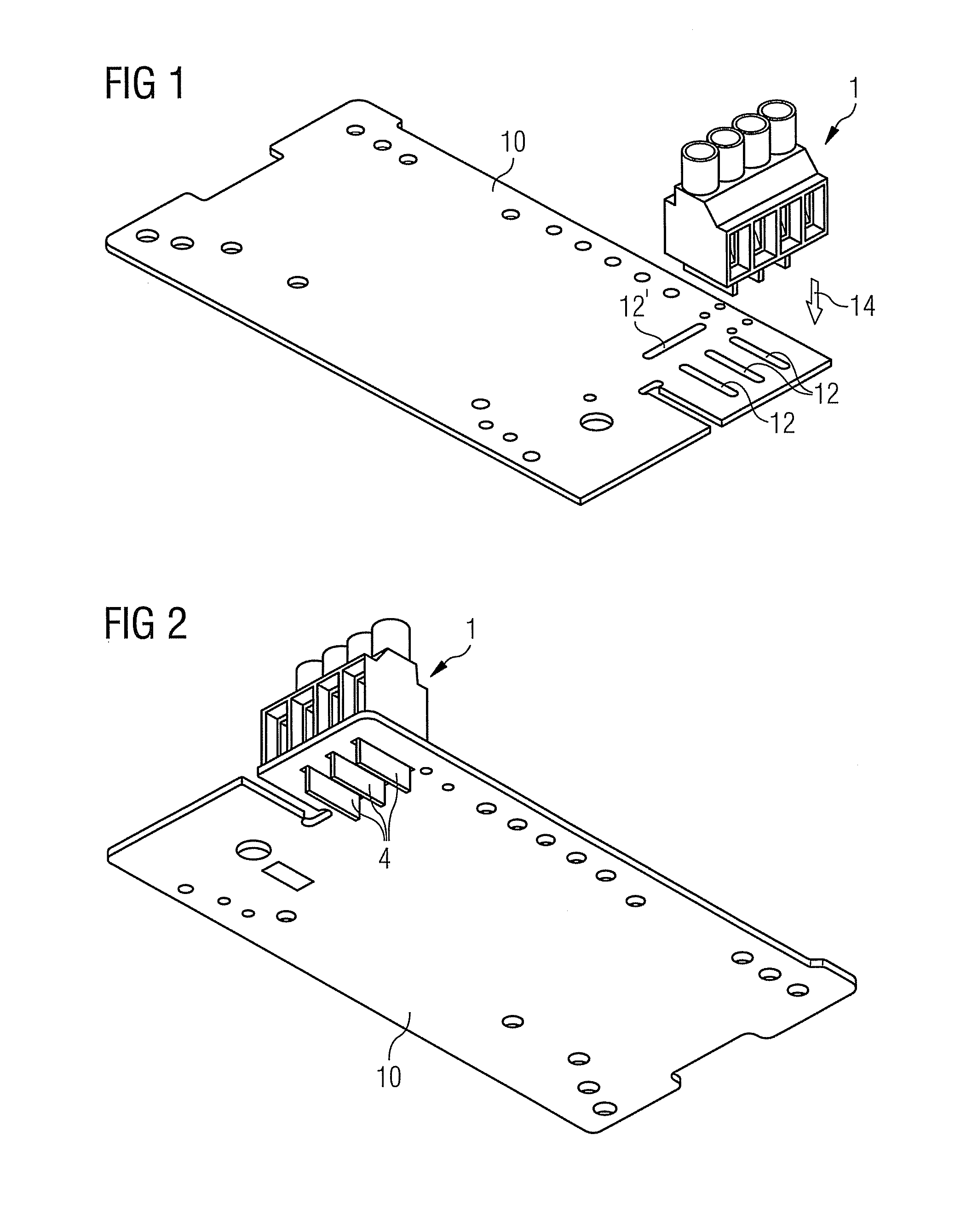
[0047]FIG. 1 shows an electrical connector element 1, which can be attached manually or in an automated manner to a printed circuit board 10 in the insertion direction 14 (see also FIG. 2).

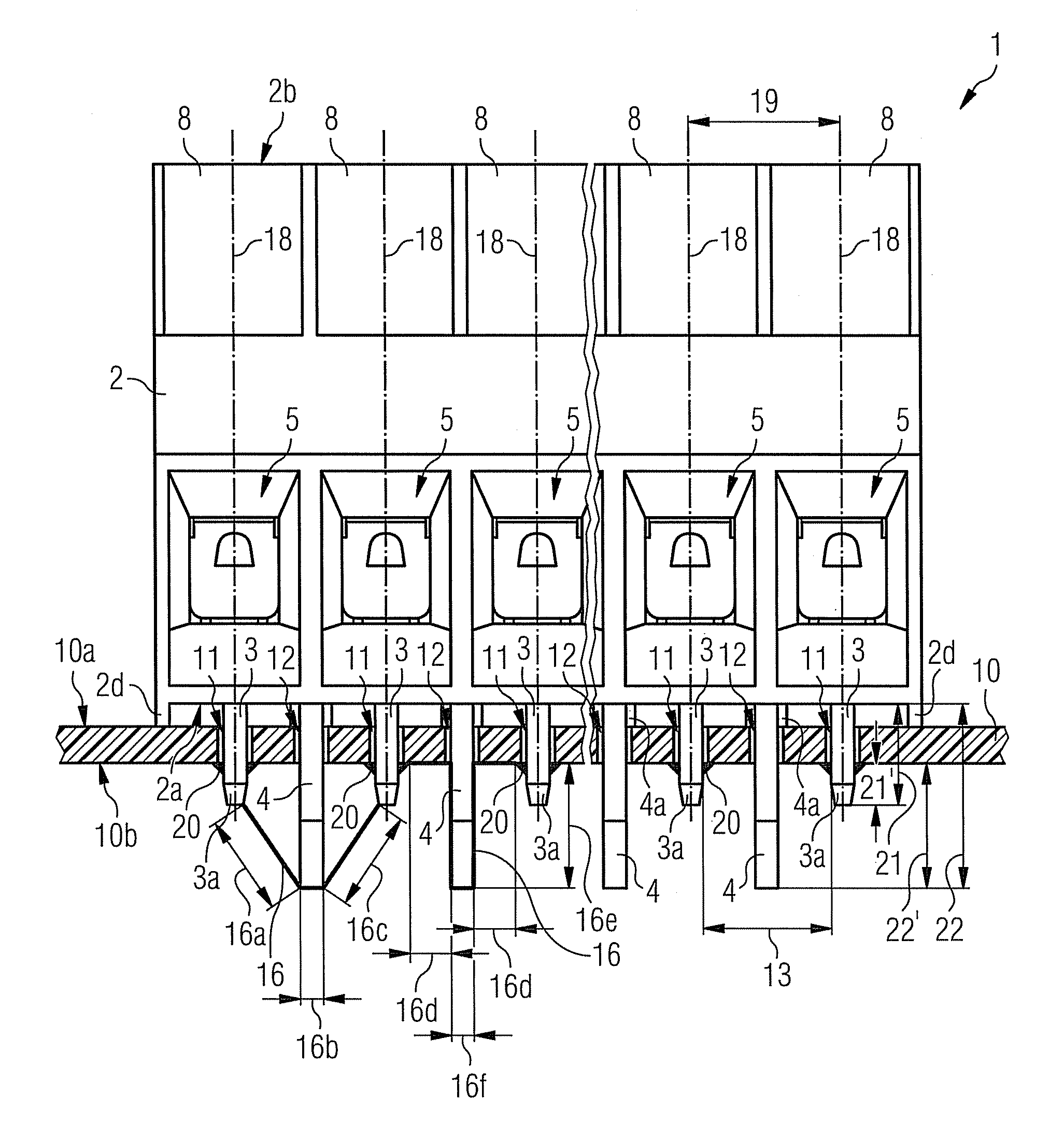
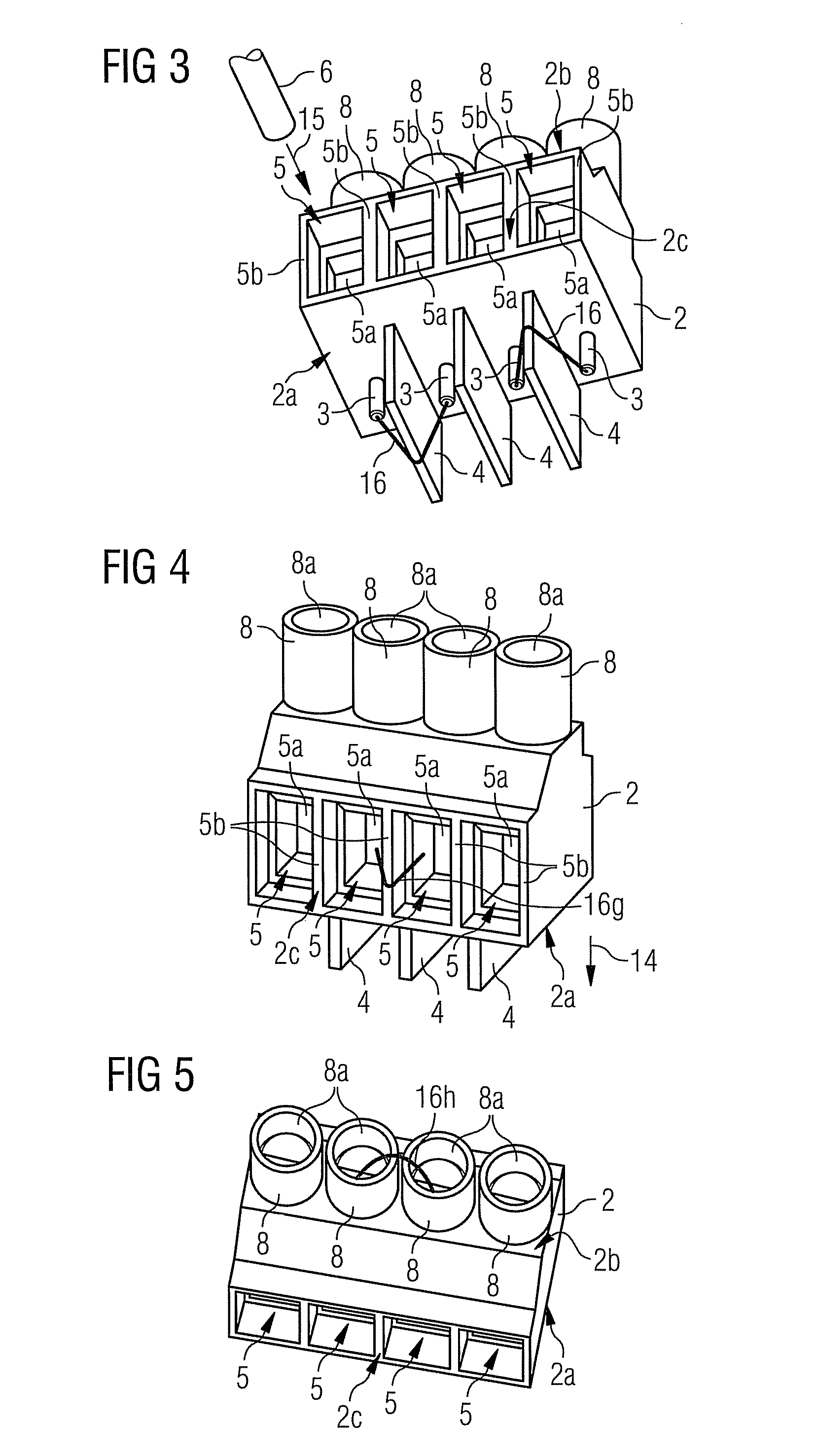
[0048]The electrical connector element 1, which can be seen in more detail in FIGS. 3 to 5, has a housing 2, which is preferably made of plastic and is provided on its front face 2c with a number of clamp connectors 5, with a holder 5a being formed respectively by web-like walls 5b. A conductor 6 can be introduced respectively into the holder 5a of the clamp connector 5 in an insertion direction 15 and can be fixed by means of actuation elements 7 disposed in the housing 2 (see sectional view in FIG. 6).

[0049]The actuation elements 7 can be screw or pressure elements for example, which bring about clamping of the conductor 6 inserted into the clamp connector 5 against a clamping cage 9 disposed in the housing 2 in the known manner.

[0050]According to FIGS. 3 to 5 the housing 2 has integrally molded...


PUM


Abstract

An electrical connector element for connection of a conductor to a circuit board, having a housing, at least one clamp connector for the conductor and at least two connector pins for preferably soldered connection to the circuit board, is disclosed. The housing has at least one separating element made from insulating material, projecting from the lower side, facing away from the circuit board in the assembled position, at least partly arranged between the connector pins and extending through the circuit board in the assembled position, in order to permit the connector pins of the electrical connector element to be arranged closer together.

Description

CROSS REFERENCE TO RELATED APPLICATIONS[0001]This application is the US National Stage of International Application No. PCT / EP2007 / 060177 filed Sep. 26, 2007 and claims the benefit thereof. The International Application claims the benefits of German Patent Application No. 10 2006 052 211.7 DE filed Nov. 6, 2006, both of the applications are incorporated by reference herein in their entirety.FIELD OF INVENTION[0002]The present invention relates to an electrical connector element for connecting a conductor to a printed circuit board or to conductor tracks disposed thereon, having a housing, at least one clamp connector for the conductor and at least two connector pins for preferably solderable connection to the printed circuit board or conductor tracks, and an arrangement having a printed circuit board with an upper face and a lower face and an electrical connector element that can be assembled on the upper face of the printed circuit board to connect a conductor, the electrical conne...

Claims


Application Information

Patent Timeline
Patent Type & Authority Patents(United States)
IPC IPC(8): H01R33/05H01R12/55
CPCH05K1/0256H05K3/306H01R12/515H01R4/366H01R9/2425H05K2201/10189H05K2201/10568H05K2203/167H05K3/3447H01R12/51H01R13/53H05K1/18H05K3/32
Inventor APPEL, WILHELMEICHHORNER, BERNHARDPEPRNY, WOLFGANGPETRICEK, MARTINSCHONLEITNER, ARNOLD
Owner SIEMENS AG
Why Eureka
Try Eureka