Guide assembly for guiding cuts to a femur and tibia during a knee arthroplasty

a technology for guiding cuts and femurs, which is applied in the field of guide assembly for guiding cuts to femurs and tibias during knee arthroplasty, can solve the problems of difficult preservation of soft tissues surrounding the knee, and achieve the effects of fast assembly and disassembly, small approach to the knee joint, and improved patient outcomes

Active Publication Date: 2011-04-19
RASMUSSEN INSTR LLC
View PDF85 Cites 44 Cited by
  • Summary
  • Abstract
  • Description
  • Claims
  • Application Information

AI Technical Summary

Benefits of technology

[0008]The present invention meets the above needs, and achieves other advantages, by providing an assembly for guiding resection of a femur and tibia of a knee joint in preparation for installing a femoral and tibial knee component. For example, the assembly can include tibial and femoral IM rods which are connected through a torque bolt that allows controlled adjustment of the distraction of the tibia and femur during cut positioning in a range of flexion angles. Also, the assembly is usable with relatively small, noninvasive approaches to the knee joint by way of relatively narrow, low profile components that attach to tibial and femoral IM rods. Further, the assembly includes several quick-release components to allow fast assembly and disassembly in a surgical setting. Each of these aspects, along with the ability of the assembly to accurately guide initial reference cuts to the tibia and femur, promotes an improved outcome for the patient.
[0010]In one aspect, the femoral mount has a cylindrical shape that extends in an anterior-posterior direction between the femoral condyles and includes a central opening and a plurality of gauge marks extending along its outside surface. The central opening may also include an anterior anti-rotation portion (e.g., a hexagonal shaped portion) and a larger diameter cylindrical portion. The tibial mount can include or support a flexion bolt with a threaded shaft at one end configured to extend into an opening in the tibial IM shaft, a bushing at the other end and an exterior hexagonal flange in between the ends. The bushing is configured to extend into the cylindrical portion and also contains an interior hexagonal bore. The hexagonal flange is configured to allow gripping by an external torque wrench or internal torque driver to urge the femoral mount away from the tibial mount (by turning of the threaded shaft) and distract the tibia and femur to a desired torque reading. This allows the surgeon to apply the appropriate amount of tension to the ligamentous structure as defined by said surgeon and recorded for comparison later in the technique.
[0013]Also included in the selectively lockable components is a quick release mechanism that is configured to slide along and lock to the ratchet bar of the flexion guide support member. For example, the quick release mechanism may define an opening configured to extend and slide along the ratchet bar, and a locking pin that is spring loaded to extend into a portion of the ratchet to stop the sliding motion. The locking pin is spring biased, but can be overcome with a manual draw pull (for example) to allow further sliding or repositioning of the quick release mechanism. The quick release mechanism may also include a spring-biased locking lever that, along with an engagement member of the quick release mechanism, can extend into an opening and lock to the flexion cutting guide. Depressing the locking lever again easily releases the flexion cutting guide after k-wire or other fasteners have been used to secure the flexion cutting guide in place to the tibia or femur. This allows the resection guide to translate toward the proximal tibia and away from the tensioning assembly with the knee in flexion.
[0014]Once the flexion resection guide is fixed to the proximal tibia, the resection guide has a plurality of slots for which to resect multiple components of the femur and tibia, most notably a measured proximal tibial resection and a posterior condylar resection. Making these resections with the knee in tension at 90 degrees will allow the user to theoretically make a tensed flexion gap resection.
[0018]The swivel arm, once referenced off the proximal tibial resection, will allow the extension cutting guide to make a pre-determined resection of the distal femur. Resecting with the knee tensed in the extended position will allow the user to make a balanced extension gap resection when compared with the tensed resections made with the knee previously positioned in flexion.
[0019]The assembly of the present invention has many advantages. For example, it provides a relatively narrow and low profile collection of locking components that securely attach cutting guides to tibial and / or femoral IM rods. This provides a robust guide to reference cuts being made to the tibia and the femur with an approach to the joint that minimizes invasiveness. Further, many of the components, such as the first and second locking mechanisms and the quick release mechanism, facilitate quick assembly, easy adjustment and quick disassembly for improved efficiency. The use of the flexion bolt in flexion, and the extension bolt and tibial angulation guide in extension, allow the tibia and femur to be distracted under a matching amount of tension in flexion and extension to ensure a better fit for the tibial and femoral knee replacement components throughout a range of flexion. Also, the tibial angulation guide allows the surgeon to adjust the amount of valgus angulation of the tibia as desired to match the anatomy of the patient.

Problems solved by technology

However, preserving the soft tissues surrounding the knee can be difficult at times due to the need to firmly support the resection guides relative to the bone of the tibia and the femur.

Method used


Image

  • Guide assembly for guiding cuts to a femur and tibia during a knee arthroplasty
  • Guide assembly for guiding cuts to a femur and tibia during a knee arthroplasty
  • Guide assembly for guiding cuts to a femur and tibia during a knee arthroplasty

Examples


Embodiment Construction

[0053]The present invention now will be described more fully hereinafter with reference to the accompanying drawings, in which some, but not all embodiments of the invention are shown. Indeed, this invention may be embodied in many different forms and should not be construed as limited to the embodiments set forth herein; rather, these embodiments are provided so that this disclosure will satisfy applicable legal requirements. Like numbers refer to like elements throughout.

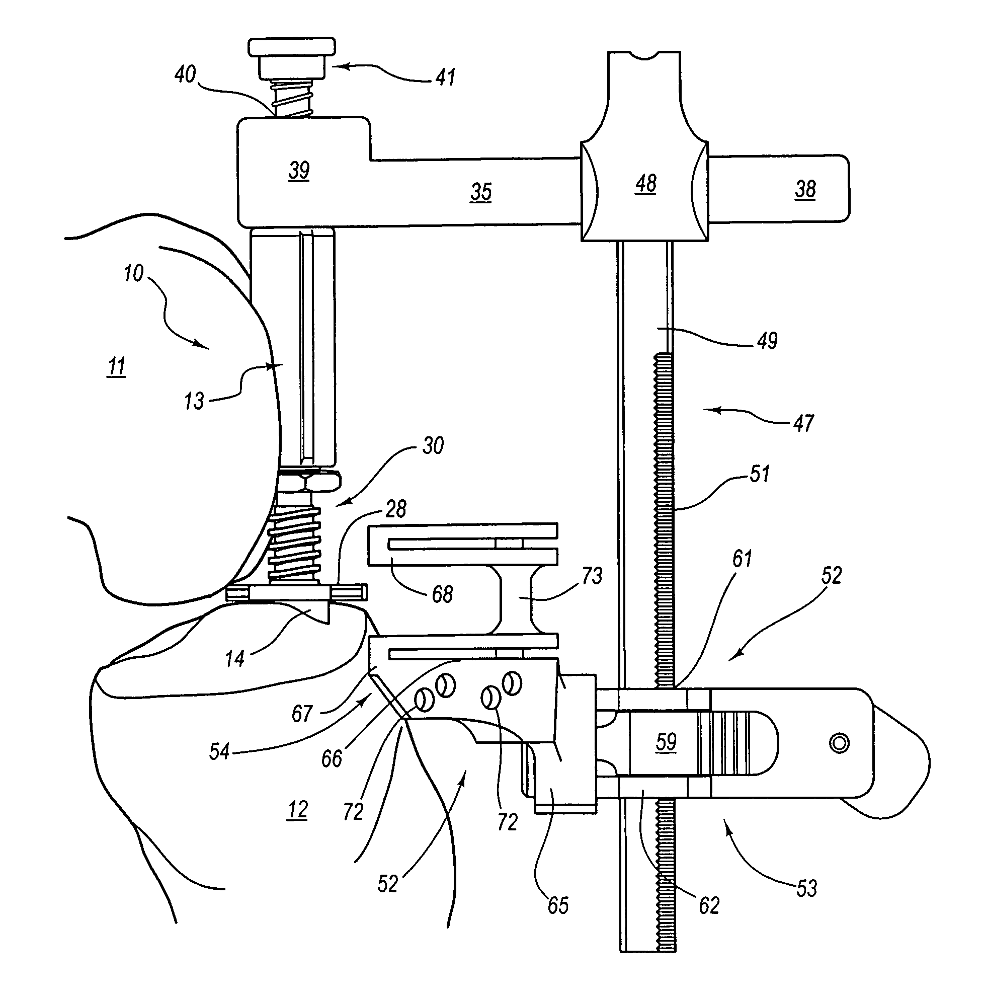
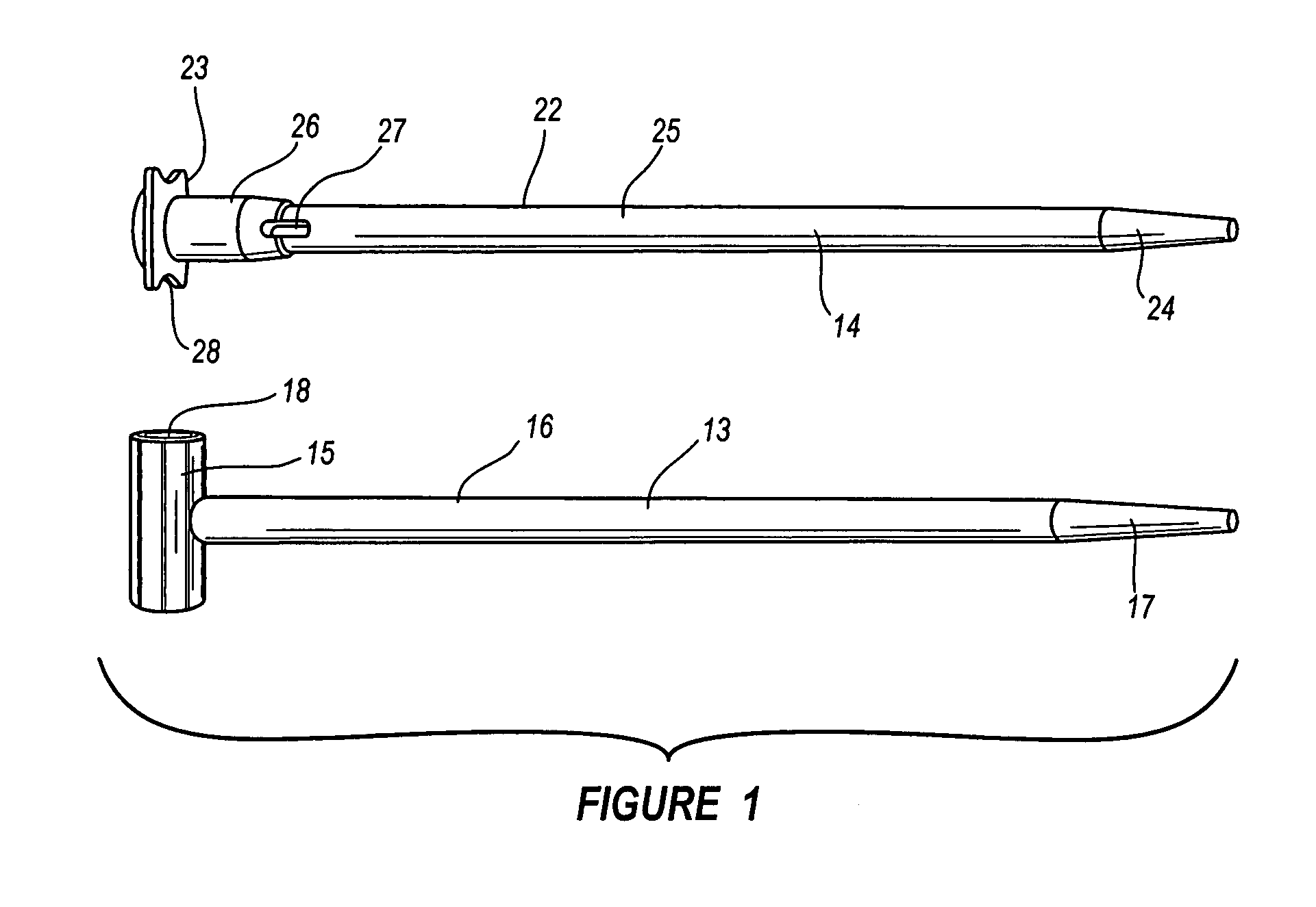
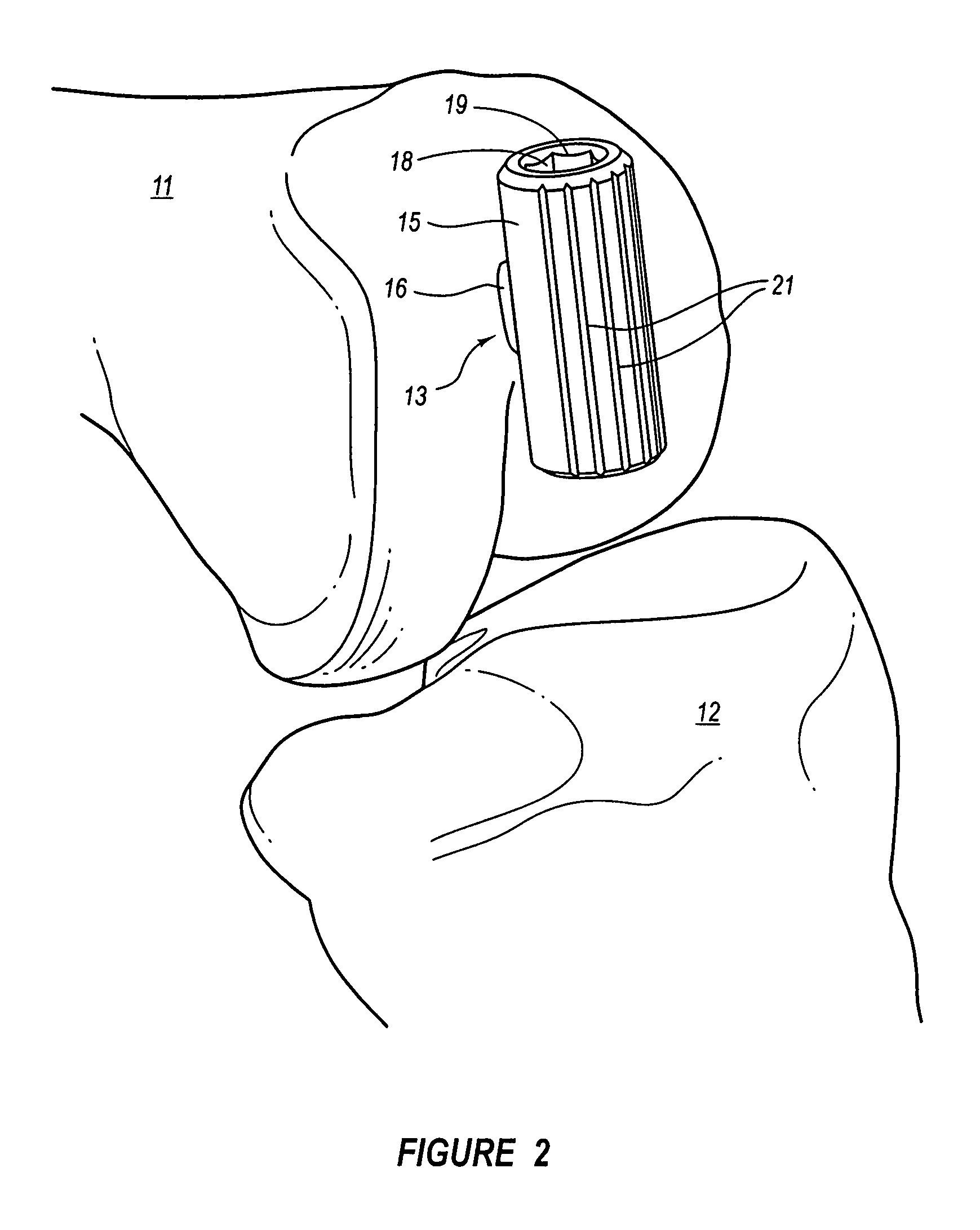
[0054]An assembly 10 of the present invention for facilitating preparation of a knee joint, including guiding positioning of cuts to a femur 11 and tibia 12 of the knee joint, for later mating with femoral and tibial knee replacement components, is shown in the accompanying figures. Generally, the assembly 10 includes various components selected and arranged to attach to a reference point inside the knee joint compartment (such as one or more intramedullary (IM) rods), extend through a relatively narrow, small or ...


PUM


Abstract

An assembly for guiding resection of a femur and tibia of a knee joint in preparation for installing a femoral and tibial knee components. For example, the assembly can include tibial and femoral IM rods to which are connected through a torque bolt that allows controlled adjustment of the distraction of the tibia and femur during cut positioning in a range of flexion angles. Also, the assembly is usable with relatively small, noninvasive approaches to the knee joint by way of relatively narrow, low profile components that attach to tibial and femoral IM rods. Further, the assembly includes several quick-release components to allow fast assembly and disassembly in a surgical setting. Each of these aspects, along with the ability of the assembly to accurately guide initial reference cuts to the tibia and femur, promotes an improved outcome for the patient.

Description

CROSS-REFERENCE TO RELATED APPLICATIONS[0001]This application claims the priority to U.S. Provisional Patent Application Ser. No. 60 / 651,102, filed Feb. 8, 2005 and entitled GUIDE ASSEMBLY FOR GUIDING CUTS TO A FEMUR AND TIBIA DURING A KNEE ARTHROPLASTY, which is hereby incorporated herein in its entirety by reference.BACKGROUND OF THE INVENTION[0002]1. Field of the Invention[0003]The present invention is related to the use of instruments for guiding preparation of a knee for installation of an implant during an arthroplasty, and in particular, to the use of ligaments around the knee and other anatomical features to position the guide instruments and making reference cuts to the tibia and the femur.[0004]2. Description of Related Art[0005]During a knee arthroplasty, a surgeon typically must gain access to the knee joint in order to perform resections of existing bone and cartilage so as to shape the tibia and femur to fit mating surfaces of the implant. Some arthroplasty procedures ...

Claims


Application Information

Patent Timeline
Patent Type & Authority Patents(United States)
IPC IPC(8): A61B17/58
CPCA61B17/025A61B17/155A61B17/157A61B2017/0268A61B17/7266A61B17/7283A61B17/8875A61B17/72A61B17/32A61B2017/00792A61B2017/320052
Inventor RASMUSSEN, G. LYNN
Owner RASMUSSEN INSTR LLC
Why Eureka
Try Eureka