
Protective helmet

a protective helmet and helmet technology, applied in the field of protective helmets, can solve the problems of not offering protection to the most common skull and brain damage, affecting the protection of the head, and a large number of subjects who call for medical attention, so as to achieve better protection against head injuries

Inactive Publication Date: 2011-04-26
K U LEUVEN RES & DEV
View PDF16 Cites 110 Cited by
  • Summary
  • Abstract
  • Description
  • Claims
  • Application Information

AI Technical Summary

Benefits of technology

The helmet reduces the risk of head and brain injuries by absorbing rotational energy, maintaining low rotational acceleration, and providing comprehensive protection against various types of impact, while maintaining comfort and ventilation.

Problems solved by technology

Epidemiological studies on accidents (e.g. bicycle accidents) show that a substantial number of the subjects who call for medical aid, are suffering from skull and brain damage.
Furthermore, cranio-cerebral traumas are a direct cause for the majority of the fatal accidents.
They are designed to satisfy legal requirements, but do generally not offer a protection to the most common skull and brain damages.
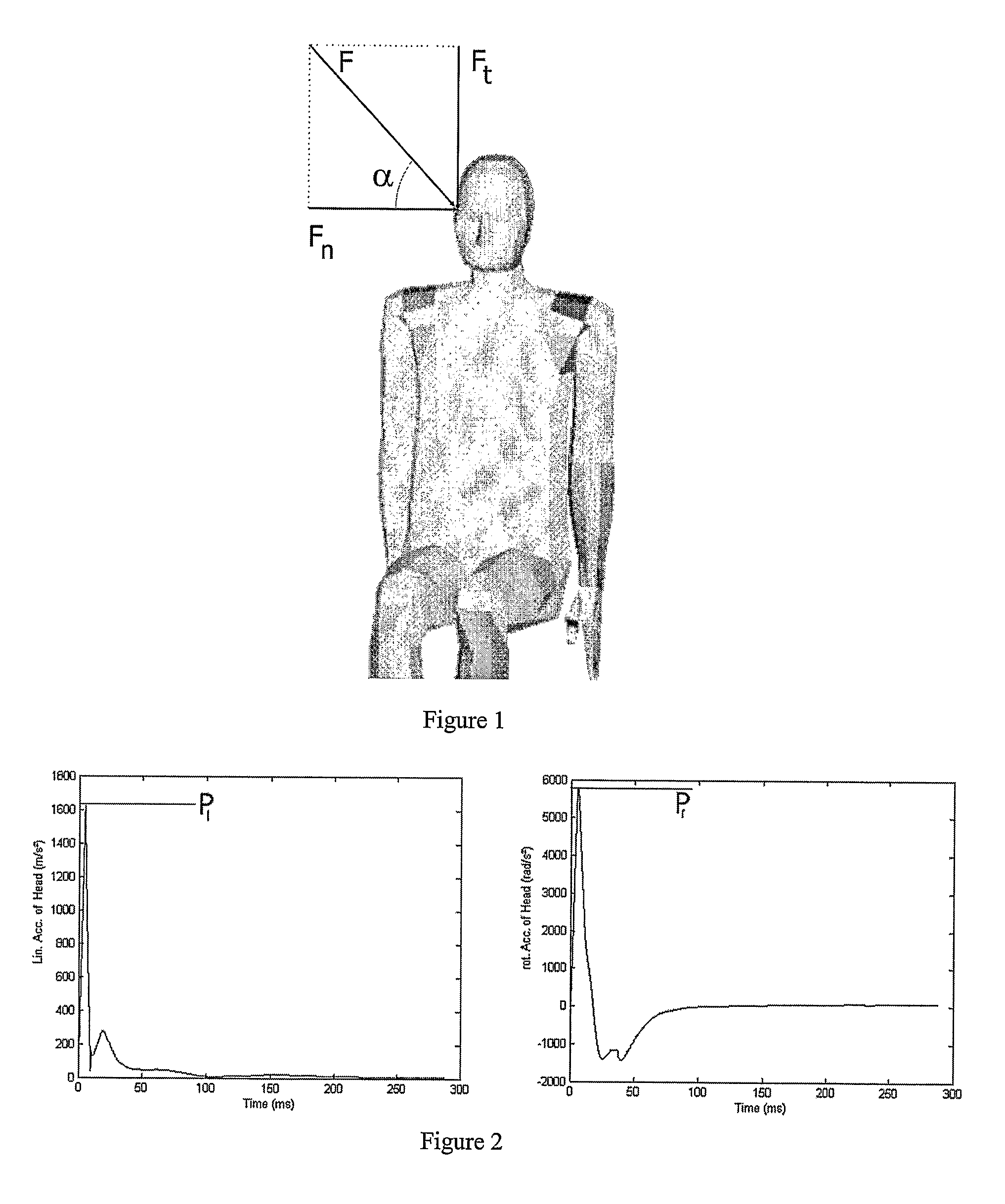
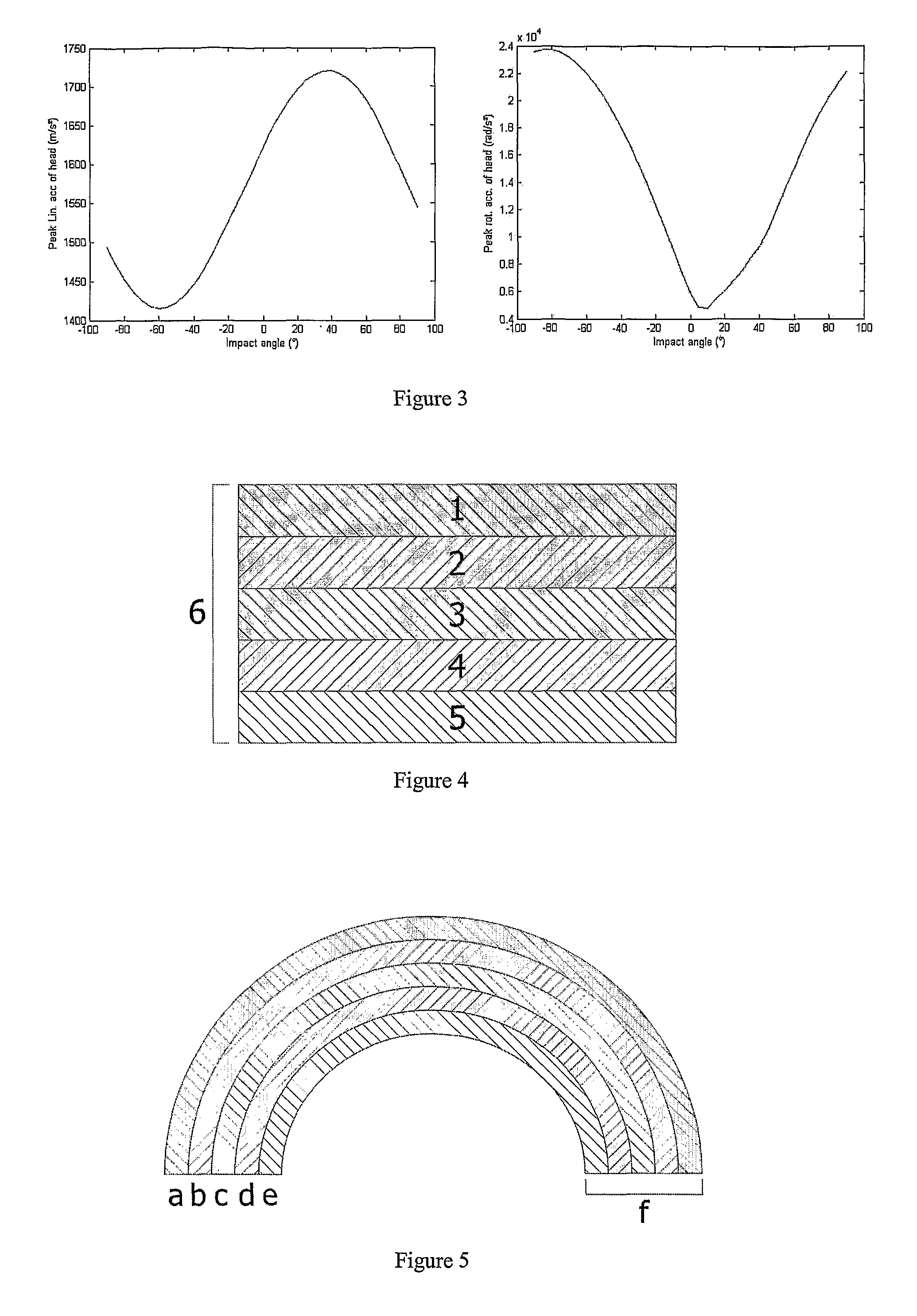
However, mathematical simulations (see FIG. 1) show that rotational accelerations of the head increase with an increasing tangential component Ft of the impact force F (see FIG. 3), while helmets that are currently available on the market do not offer a sufficient protection against impact that is tangential to the head.
These helmets, however, only allow a limited rotational displacement of the inner shell with respect to the outer shell, because the shape of the helmet is not a perfect hemisphere.
Consequently, the energy that can be dissipated is limited as well.
Furthermore, these helmets have poor ventilation capacities, and are relatively complex to manufacture.

Method used


Image

  • Protective helmet
  • Protective helmet
  • Protective helmet

Examples


Embodiment Construction

[0031]The present invention will be described with respect to particular embodiments and with reference to certain drawings but the invention is not limited thereto but only by the claims. Any reference signs in the claims shall not be construed as limiting the scope. The drawings described are only schematic and are non-limiting. In the drawings, the size of some of the elements may be exaggerated and not drawn on scale for illustrative purposes. Where the term “comprising” is used in the present description and claims, it does not exclude other elements or steps. Where an indefinite or definite article is used when referring to a singular noun e.g. “a” or “an”, “the”, this includes a plural of that noun unless something else is specifically stated.

[0032]Furthermore, the terms first, second, third and the like in the description and in the claims, are used for distinguishing between similar elements and not necessarily for describing a sequential or chronological order. It is to be...


PUM

PropertyMeasurementUnit
forcesaaaaaaaaaa
speedaaaaaaaaaa
forceaaaaaaaaaa

Abstract

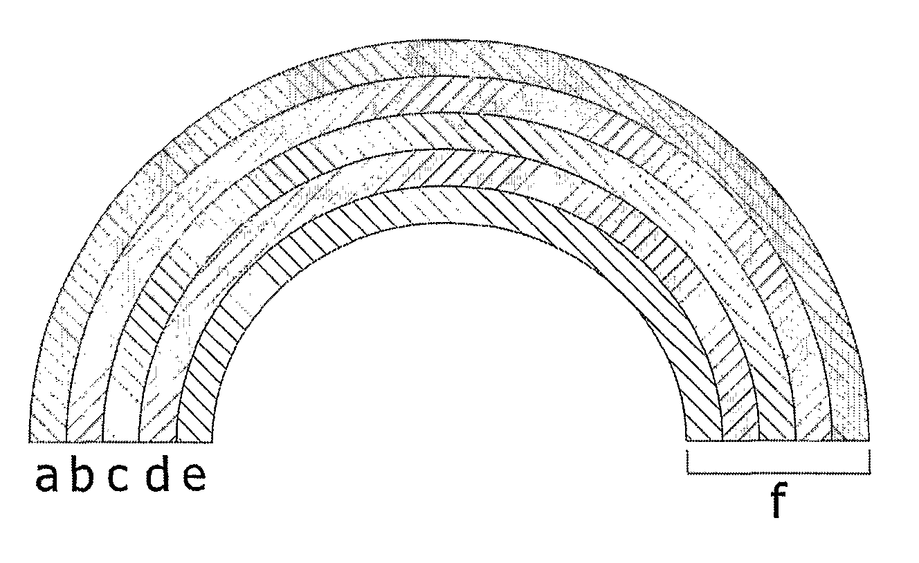
A protective helmet is described comprising: an outer layer (1); an inner layer (5) for contact with a head of a wearer; and an intermediate layer (3, 4) comprising an anisotropic cellular material comprising cells having cell walls, the anisotropic cellular material having a relatively low resistance against deformation resulting from tangential forces on the helmet. The anisotropic material can be a foam or honeycomb material. The foam is preferably a closed cell foam. The helmet allows tangential impacts to the helmet which cause less rotational acceleration or deceleration of the head of the wearer compared to helmets using isotropic foams while still absorbing a significant amount of rotational energy.

Description

FIELD OF THE INVENTION[0001]The present invention relates to a protective helmet, such as a helmet which can be worn by a cyclist, motorcyclist, pilot, bobsleigh sportsperson, etc. to protect against injury as well as a method of manufacture thereof.BACKGROUND OF THE INVENTION[0002]Epidemiological studies on accidents (e.g. bicycle accidents) show that a substantial number of the subjects who call for medical aid, are suffering from skull and brain damage. Furthermore, cranio-cerebral traumas are a direct cause for the majority of the fatal accidents. A protection helmet should therefore protect the head against these traumas.[0003]There are many types of protective helmets on the market, with different designs and characteristics. They are designed to satisfy legal requirements, but do generally not offer a protection to the most common skull and brain damages. At present, these legal requirements are related to the maximum linear acceleration that may occur in the centre of gravit...

Claims


Application Information

Patent Timeline
Patent Type & Authority Patents(United States)
IPC IPC(8): A42B3/00A42B3/06A42B3/12
CPCA42B3/124A42B3/064A42B3/128
Inventor DEPREITERE, BARTGOFFIN, JANVAN LIERDE, CARLHAEX, BARTVANDER SLOTEN, JOSVAN AUDEKERCKE, REMYVAN DER PERRE, GEORGEVERPOEST, IGNACEVERSCHUEREN, PETERDELYE, HANS
Owner K U LEUVEN RES & DEV
Learn More