
Separators for alkaline electrochemical cells

a technology of electrochemical cells and separation devices, applied in the field of separation devices for alkaline electrochemical cells, can solve the problems of reducing the efficiency of modern electronic devices, so as to reduce the migration of anode-fouling soluble species, effectively limit the migration and reduce the effect of soluble copper species

Active Publication Date: 2011-04-26
ENERGIZER BRANDS
View PDF442 Cites 35 Cited by
  • Summary
  • Abstract
  • Description
  • Claims
  • Application Information

AI Technical Summary

Benefits of technology

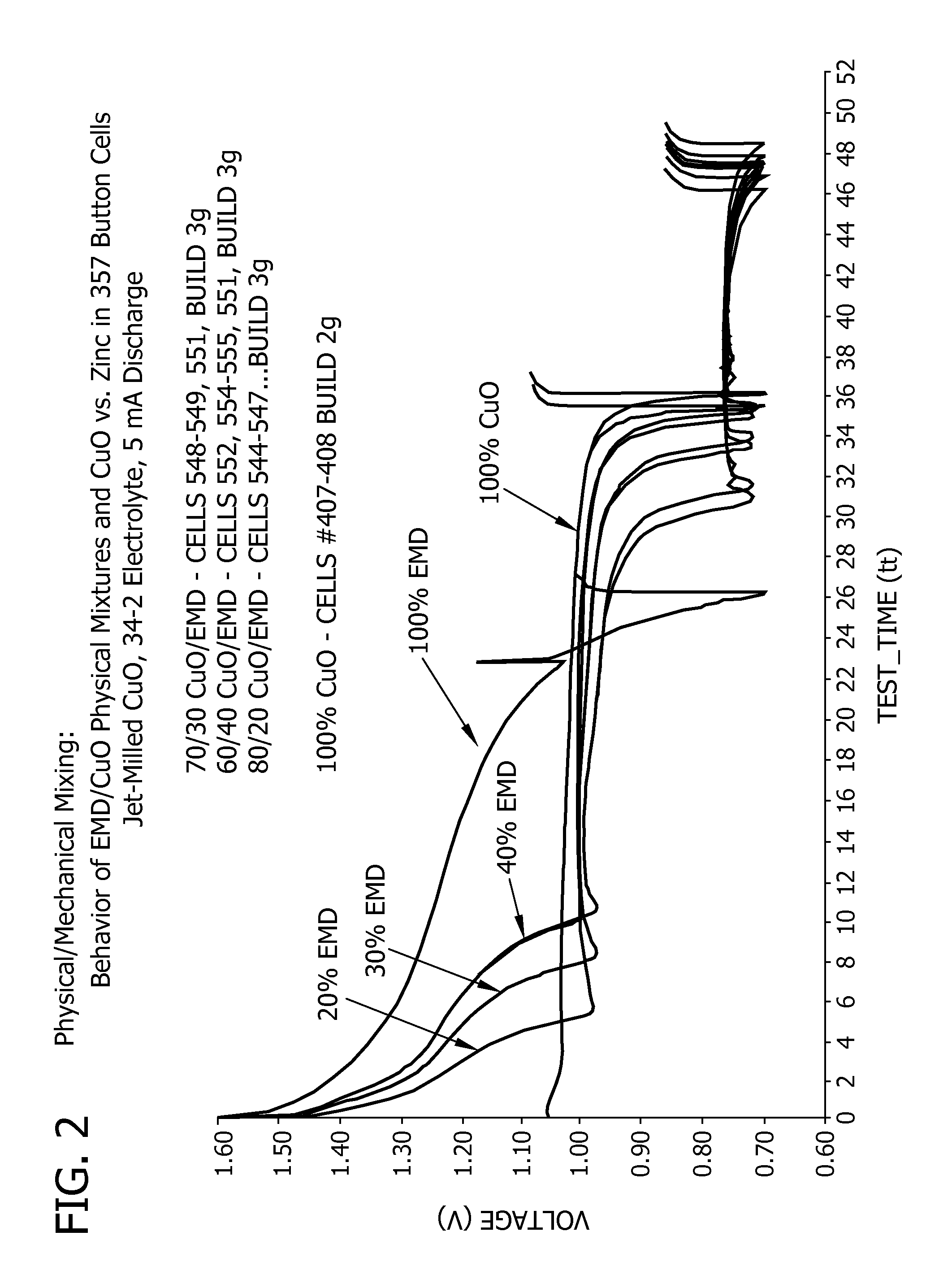
[0072]In accordance with an embodiment of this method, CuO and Ag2O are precipitated from CuSO4 and AgNO3, respectively in alkali media in the presence of EMD. The cathode material can contain for example, 64% CuO, 35% EMD and approximately 1% Ag2O added as a conductivity enhancer. The Ag2O will discharge first, producing highly conducting metallic silver in the cathode. Synthetic, natural or expanded graphites as are well known in the art provide adequate electronic conductivity and integrity to the cathode. The resulting cathode, shown in FIG. 5, shows significant increase in the initial voltage, while providing discharge capacity significantly greater than the MnO2. The flat portion of the discharge is also approximately 45 mV higher on average, than the voltage of CuO alone. The transition from MnO2 behavior to CuO behavior is also smoother in FIG. 5 than is the transition in FIG. 2. It is an advantage of the present invention that discharge capacity of the cell is higher than in conventional cells over a range of discharge rates.
[0073]In the third general approach, supplementary additives can also be chosen for combining, from elements or compounds that have a lower discharge voltage than CuO, but which, in combination with CuO, produce a higher discharge voltage than either constituent alone. When the reaction kinetics are suitably rapid, the discharge voltage of these couples also follows the same trend as the open circuit voltage. Examples of such materials may include, but are not limited to, elemental sulfur, selenium, tellurium, sulfides, selenides, tellurides, and iodates such as CuS, Ag2S, ZnS, B2S3, SnS, FeS, Fe2S3, CoS, NiS, CuSe, CuTe, CuAgS, CuAg3S, and suitable compounds and mixtures thereof. For example, it is believed for the case of a CuO / CuS combination, that the discharge voltage is unexpectedly higher as a result of a displacement reaction between CuO and CuS (i.e., CuS having a discharge voltage lower than CuO). Thus, while pure CuS by itself has a lower discharge voltage versus zinc (0.7V vs. Zn), the combination of CuS with CuO discharges at a higher voltage than either material by itself. Shown below are theoretical open circuit voltages for relevant reactions to help illustrate the CuO / CuS system:
[0074]Copper Oxide Reduction Reaction: (Reaction I)2CuO+2e+H2O→Cu2O+2OH− ΔG=−50.2 K cal
[0076]Copper Sulfide Reduction Reaction (Reaction 2)2CuS+2e+H2O→Cu2S+HS−+OH− ΔG=−32.6 K cal
[0078]Copper Oxide / Copper Sulfide Mixture Reduction Reaction: (Reaction 3)CuO+CuS+2e+H2O→Cu2S+2OH− ΔG=−54.6 K cal
[0080]To determine the change in Free Energies and Open Circuit Voltages above, the anode reaction used was:Zn+20H−→ZnO+H2O+2e

Problems solved by technology

However, the low density of the manganese dioxide material and its consumption of water during the discharge reaction of conventional zinc manganese dioxide alkaline electrochemical cells (requiring the designer to provide the necessary water) limits the amount of space available for the zinc anode (which determines the service life), thereby leading to relatively low volumetric energy density.
Although it appears to be an excellent candidate for a long service life battery, the operating voltage of conventional batteries having a zinc anode and a copper oxide cathode is unfortunately no more than approximately 1.05V, too low to operate modern day electronic devices at reasonable current drains.
At any substantial device current drain, it can fall significantly below 1V, rendering the device largely inoperable.
However, it is recognized in the art that soluble sulfur species produced in the presence of alkaline electrolyte are detrimental to both anode performance and shelf life.
The commercial application is therefore limited.
Notably many of the prior approaches fail to mention soluble copper species that can be detrimental to the anode, provide no means for mitigating the problem, and fail to recognize the significance of surface area of CuO particles or of active sites on the particles on the cell discharge voltage and performance.
Therefore, the disclosed technology does not produce a viable battery with reasonable shelf life.

Method used

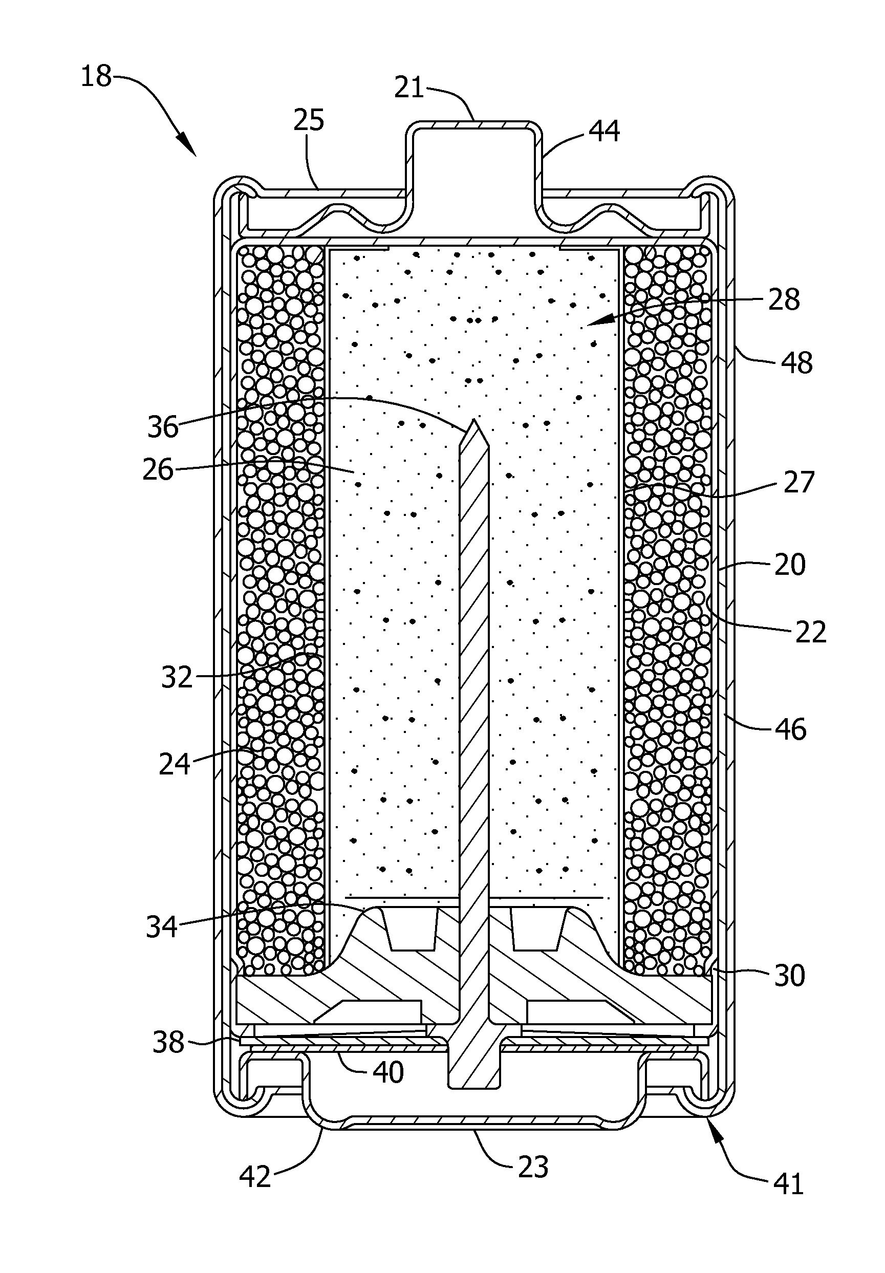
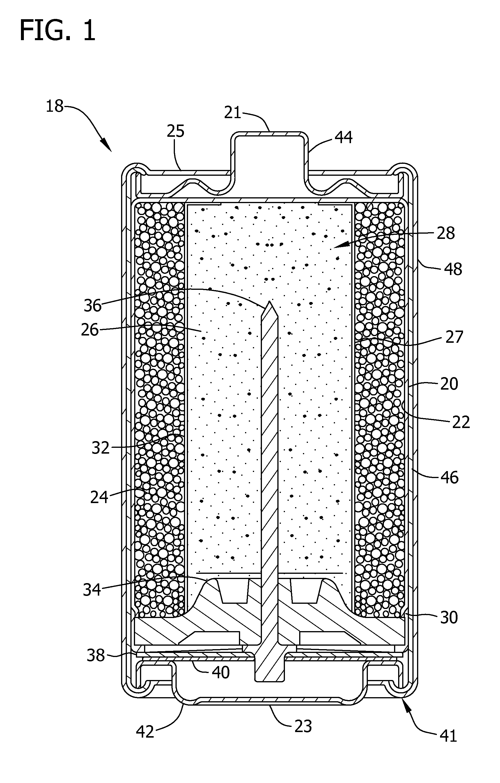

Image

  • Separators for alkaline electrochemical cells
  • Separators for alkaline electrochemical cells
  • Separators for alkaline electrochemical cells

Examples


example 1

[0192]This is an example that illustrates the efficacy of various separators' ability to effectively limit the migration of anode-fouling soluble species. The OCV was compared for a plurality of 357 cells made with various separators both initially and after 1 day room temperature of storage. The cathode was CuO (commercially available from Aldrich), and the cell anode was a conventional alkaline Zn gel anode having conventional zinc and electrolyte concentrations.

[0193]In most cases, two layers of separator were used in the cell, one facing the cathode (“cathode side separator”), the other facing the anode (“anode side separator”). The OCV data presented below in Table 3 includes the average of two cells of the given cell type. It should be appreciated that a decrease in OCV indicates increased migration of anode-fouling soluble copper species into the anode.

[0194]

TABLE 3Cathode Side SeparatorAnode SideOCV, VOCV, VCategoryTypeSeparator(initial)(after 1 day)Cellophane350P00FS22131.1...

example 2

[0196]This is an example that illustrates the ability of various separators to effectively limit the migration of anode-fouling species. As explained elsewhere, Side A of the glass tube fixture was filled with 34% KOH having a known concentration of copper ions and electrolyte free of copper ions was added to compartment B. The concentration of complex copper ions on side B was measured after 1 week at room temperature.

[0197]Referring now to Table 4, the Exclusion Test was performed on various separators to determine the Exclusion Value of soluble copper, silver, and sulfur species after storage at a temperature of 60 C. Side A of the glass fixture was filled with 34% KOH solution with 0.25 g of CuO (copper oxide) and 0.25 g of CuS powder which produce the soluble copper and sulfur species concentrations shown in columns 2 and 4. For silver exclusion determination, 0.25 g of AgO was used in side A of the AgO was used in side A of the fixture to produce silver concentrations shown in...

example 3

[0200]This is an example that illustrates the utility of effectively limiting the migration of anode-fouling soluble species in stored 357 size button cells. Referring now to FIG. 20, four cells having CuO cathodes were stored for five days at room temperature, followed by 60 degrees C. until the cells failed (as determined by OCV, impedance and expansion as discussed previously). The OCV was continuously measured for each cell from the first day of storage. FIG. 20 shows that cellophane separators are better than FAS 350Z separator for cells containing CuO cathodes. Also, thicker cellophane separators (SF-586, 3 mil thick) outperform the thinner separator (350P00, and SC216 both are 1 mil thick) confirming results from the Exclusion Test experiments.


PUM

PropertyMeasurementUnit
temperatureaaaaaaaaaa
thicknessaaaaaaaaaa
thicknessaaaaaaaaaa

Abstract

The present invention relates to a high capacity electrochemical cell having a cathode containing an oxide of copper as an active material, as well as an anode, an electrolyte, and separators for use with the cathodes of the invention in an alkaline electrochemical cell.

Description

CROSS REFERENCE TO RELATED APPLICATIONS[0001]This application is a continuation of U.S. patent application Ser. No. 10 / 914,934 filed Aug. 9, 2004, now U.S. Pat. No. 7,645,540, which claims the benefit of U.S. Provisional Patent Application Ser. No. 60 / 493,695 filed Aug. 8, 2003, U.S. Provisional Patent Application Ser. No. 60 / 528,414 filed Dec. 10, 2003, and U.S. Provisional Patent Application Ser. No. 60 / 577,292 filed Jun. 4, 2004, the disclosure of each of which is hereby incorporated by reference as if set forth in their entirety herein.STATEMENT REGARDING FEDERALLY SPONSORED RESEARCH & DEVELOPMENT[0002]The U.S. Government has a pre-paid license in this invention and the right in limited circumstances to require the patent owner to license others on reasonable terms as provided for by the terms of Contract No. 99128200.BACKGROUND OF THE INVENTION[0003]Alkaline electrochemical cells are typically configured as elongated cylindrical cells (e.g., AA-, AAA-, C- and D-size cells) or a...

Claims


Application Information

Patent Timeline
Patent Type & Authority Patents(United States)
IPC IPC(8): H01M2/16H01M4/485H01M2/08H01M4/02H01M4/16H01M4/24H01M4/32H01M4/42H01M4/48H01M4/54H01M4/56H01M4/58H01M4/62H01M10/24H01M10/26
CPCH01M4/48H01M4/5825H01M10/24Y02E60/124H01M2004/021Y02E60/10
Inventor BOONE, DAVIDBUSHONG, WILLIAM C.CHEESEMAN, PAULDAVIDSON, GREGORY J.DESTEPHEN, MARIOJIN, ZHIHONGLUECKE, JONMORTENSEN, ERIKNDZEBET, ERNESTRAMASWAMI, KARTHIKSAZHIN, SERGIY V.VU, VIET H.
Owner ENERGIZER BRANDS
Learn More