Tunneling magnetic sensor including free magnetic layer and magnesium protective layer disposed thereon

a magnetic sensor and free magnetic technology, applied in the field of magnetic sensors, can solve the problems of low stability of reproducing heads, low magnetostric ineffective adjustment of free magnetic layers to achieve low magnetostriction to achieve large changes in reluctance, so as to prevent the magnetostriction of free magnetic layers, the effect of manufacturing appropriately and readily

Active Publication Date: 2011-04-26
TDK CORPARATION
View PDF7 Cites 17 Cited by
  • Summary
  • Abstract
  • Description
  • Claims
  • Application Information

AI Technical Summary

Benefits of technology

[0031]Therefore, the tunneling magnetic sensor can be manufactured appropriately and readily so as to have a large change in reluctance with the magnetostriction of the free magnetic layer being prevented.

Problems solved by technology

One of challenges for tunneling magnetic sensors is to enhance the sensitivity by increasing the change in reluctance to enhance properties of reproducing heads.
An increase in the absolute value of the magnetostriction of the free magnetic layers causes noise in the reproducing heads, resulting in a problem that the reproducing heads have low stability.
As described above, the magnetostriction can be reduced by adjusting the material composition of the free magnetic layer or using such a low-magnetostriction alloy; however, the composition of the free magnetic layer that is adjusted to achieve low magnetostriction is not effective in achieving a large change in reluctance.
Therefore, this tunneling magnetic sensor has low magnetostriction and a large change in reluctance.
However, the change in reluctance thereof is still insufficient.
The conventional structures described above are not effective in achieving low magnetostriction and a large change in reluctance.

Method used


Image

  • Tunneling magnetic sensor including free magnetic layer and magnesium protective layer disposed thereon
  • Tunneling magnetic sensor including free magnetic layer and magnesium protective layer disposed thereon
  • Tunneling magnetic sensor including free magnetic layer and magnesium protective layer disposed thereon

Examples


examples

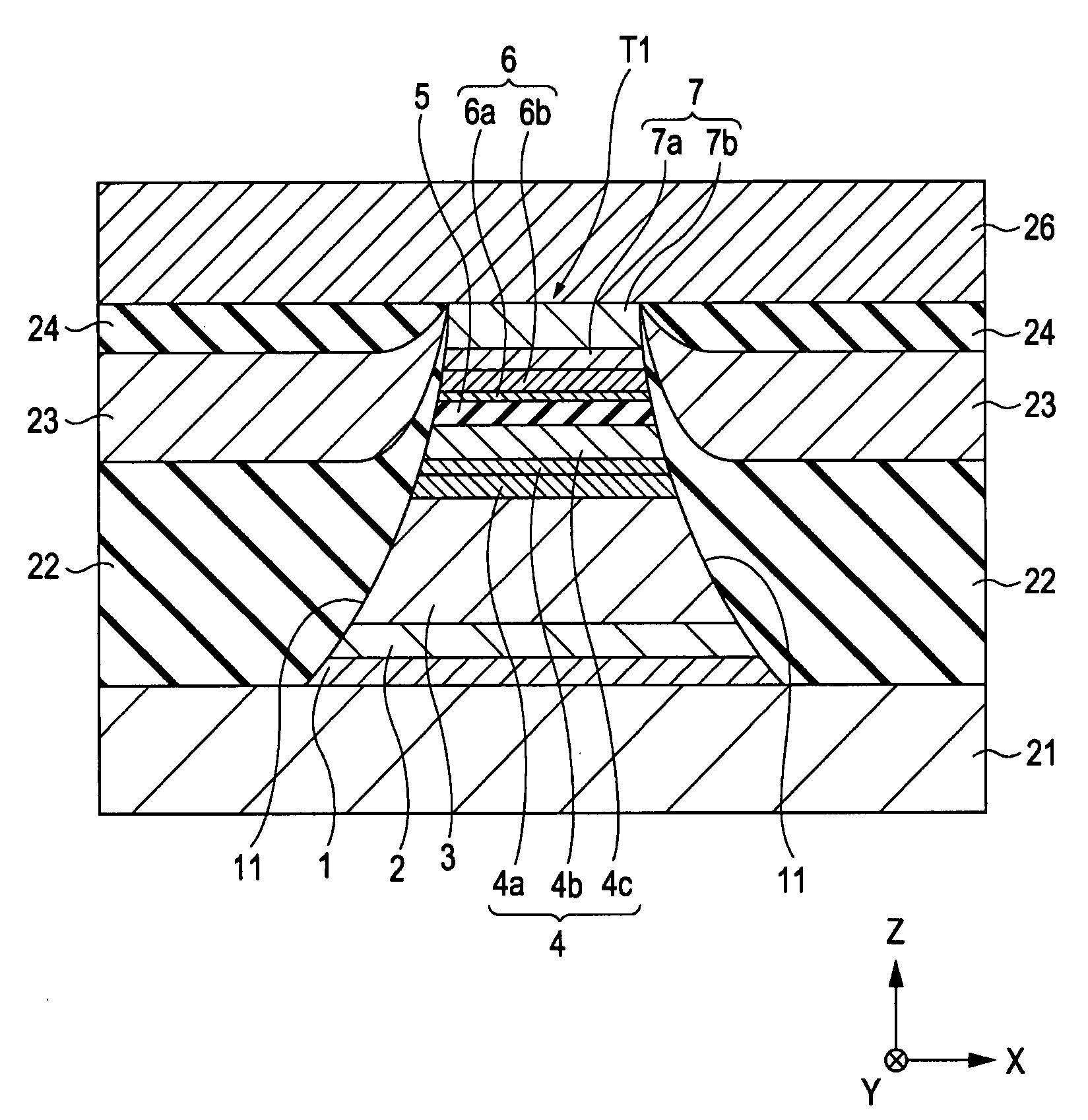
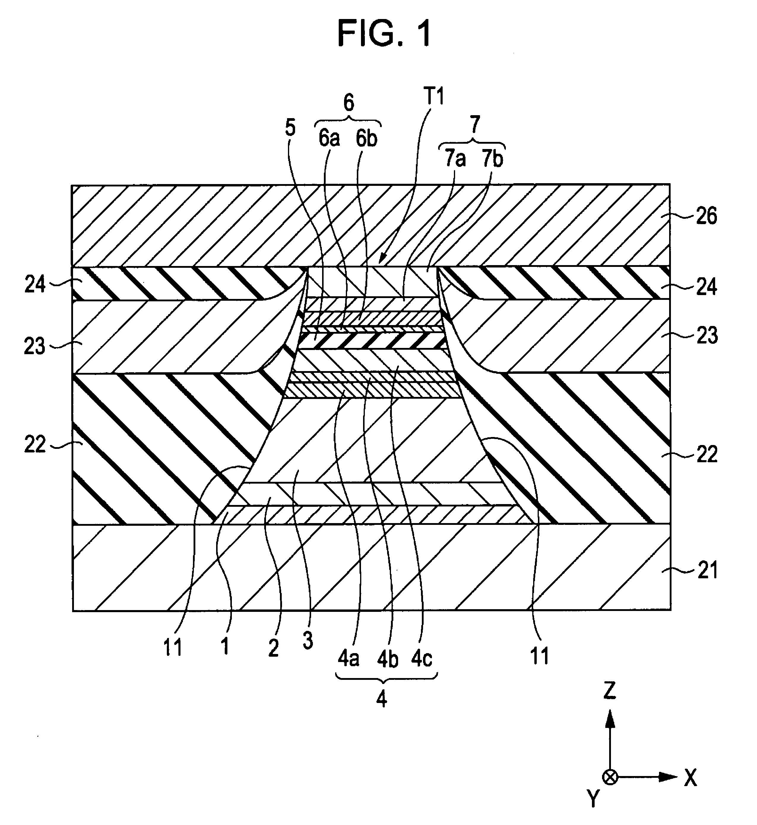
[0095]Tunneling magnetic sensors were prepared so as to have configurations similar to the configuration of the tunneling magnetic sensor shown in FIG. 1.

[0096]In Example 1, a tunneling magnetic sensor including an insulating barrier layer 5 made of Al—O was prepared as described below.

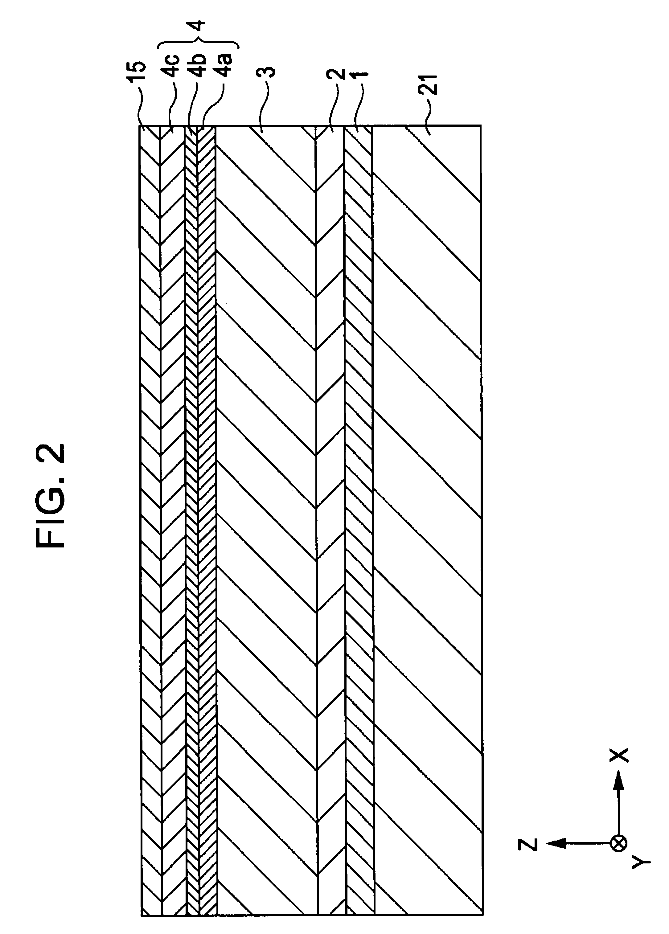
[0097]The following layers were deposited on a lower shield layer 21 in this order: a base layer 1, made of Ta, having an average thickness of about 80 Å; a seed layer 2, made of a Ni—Fe—Cr alloy, having an average thickness of about 50 Å; an antiferromagnetic layer 3, made of an Ir—Mn alloy, having an average thickness of about 70 Å; a pinned magnetic layer 4 including a first pinned magnetic sublayer 4a which contained about 70 atomic percent Co and 30 atomic percent Fe and which had an average thickness of about 14 Å, a non-magnetic intermediate sublayer 4b which was made of Ru and which had an average thickness of about 9.1 Å, and a second pinned magnetic sublayer 4c which contained about 60 atomi...


PUM

PropertyMeasurementUnit
temperatureaaaaaaaaaa

Abstract

A tunneling magnetic sensor includes a pinned magnetic layer of which the magnetization is pinned in one direction, an insulating barrier layer, and a free magnetic layer of which the magnetization is varied by an external magnetic field, these layers being arranged in that order from the bottom. A first protective layer made of magnesium (Mg) is disposed on the free magnetic layer. The tunneling magnetic sensor has a larger change in reluctance as compared to conventional magnetic sensors including no first protective layers or including first protective layers made of Al, Ti, Cu, or an Ir—Mn alloy. The free magnetic layer has lower magnetostriction as compared to free magnetic layers included in the conventional magnetic sensors.

Description

CLAIM OF PRIORITY[0001]This application claims benefit of the Japanese Patent Application No. 2006-234464 filed on Aug. 30, 2006, which is hereby incorporated by reference.BACKGROUND OF THE INVENTION[0002]1. Field of the Invention[0003]The present invention relates to magnetic sensors, using tunnel effect, for magnetic detecting devices or magnetic storage devices such as hard disk drives. The present invention particularly relates to a tunneling magnetic sensor which includes a free magnetic layer having low magnetostriction (λ) and which has a large change in reluctance (ΔR / R), high detection sensitivity, and high stability and also relates to a method for manufacturing the tunneling magnetic sensor.[0004]2. Description of the Related Art[0005]A tunneling magnetic sensor (tunneling magnetoresistive element) causes a change in reluctance using tunnel effect. When the magnetization of a pinned magnetic layer is antiparallel to that of a free magnetic layer, a tunnel current is preve...

Claims


Application Information

Patent Timeline
Patent Type & Authority Patents(United States)
IPC IPC(8): G11B5/39
CPCB82Y10/00B82Y25/00G01R33/093G01R33/098G11B5/3906H01F10/3295H01F10/3254H01F41/32H01L43/08H01L43/12G11B5/3909H01F10/3272H10N50/01H10N50/10
Inventor NAKABAYASHI, RYONISHIMURA, KAZUMASAIDE, YOSUKEISHIZONE, MASAHIKOSAITO, MASAMICHIHASEGAWA, NAOYA
Owner TDK CORPARATION
Why Eureka
Try Eureka