Methods of manufacturing electrical cables

a manufacturing method and cable technology, applied in the direction of insulated conductors, power cables, cables, etc., can solve the problems of insulation not being able to penetrate into the spaces between the conductor strands, insulation being bulging, insulation to burst, etc., to achieve high coverage and eliminate interstitial spaces

Active Publication Date: 2011-05-03
SCHLUMBERGER TECH CORP
View PDF12 Cites 27 Cited by
  • Summary
  • Abstract
  • Description
  • Claims
  • Application Information

AI Technical Summary

Benefits of technology

[0019]Embodiments of methods provide cables with continuously bonded polymer layers, with substantially no interstitial spaces, for applications ranging from stranded conductors to served shield conductors, to armor wire systems for monocables, coaxial cables, heptacables and seismic cables. With armor wire systems, this may consist of a continuous jacket, extending from the cable core to the cable's outer diameter, while maintaining a high percentage of coverage by the armor wire layers. The jacket system encapsulates the armor wires and substantially eliminates interstitial spaces between armor wires and jacketing (or between conductor strands and insulation) that might serve as conduits for gas migration. Embodiments of methods enable cabled metallic components (such as conductor strands or armor wires) to be applied over and partially embed into slightly melted polymers. The methods include cabling the components over freshly extruded and or semi cooled extruded polymer and / or passing the polymer through a heat source like infrared (IR) substantially immediately prior to cabling, and / or using heat induction to heat the metallic components sufficient to allow them to melt the polymer and partially embed into the polymer's surface and / or using an electromagnetic heat source (for example, infrared waves) to partially melt the jacketing material very soon after each conductor strands or armor wire layer is applied over a jacket layer. This allows conductor strands or armor wires to embed in the polymeric insulation or jacketing materials, locking the armor wires in place and virtually eliminates interstitial spaces. Embodiments also comprise machines for practicing embodiments of the methods including, but not limited to, an armoring machine comprising an armor machine housing having a cable conductor inlet and outlet and at least one spool disposed within the housing and having a supply of armor wire spooled thereon for dispensing the armor wire for cabling, the spool operable to rotate with respect to the housing to allow the cable conductor to pass therethrough.

Problems solved by technology

The insulation is not able to penetrate into the spaces between the conductor strands.
When the cable is being pulled out of the wellbore at high speed, these gases can decompress, leading to bulging insulation.
If the gases decompress rapidly, this can even cause the insulation to burst, through the phenomenon of explosive decompression.
Problems with gas migration through interstitial spaces are also observed in coaxial cables and individual insulated conductors.
Because these wires do not “dig in” sufficiently to the central conductor's insulation, individual wires can become raised up above the other wires and “milk back” during the manufacturing process, damaging the cable.
Individual wires can also cross over each other, causing high spots in the served shield, which can lead to similar damage.
The cable can be damaged when this pressurized gas is released through weak spots in the jacket through explosive decompression.
It also compromises separation between the served shield and the armor wires.
As the wireline goes over the upper sheave at the top of the piping, the armor wires tend to spread apart slightly and the pressurized gas is disadvantageously released.
Because of the space between the armors, the armors tend to milk or cross over one another during manufacture, and are not uniformly spaced.
Non-uniform armor spacing can lead to weak spots in the completed cables.
In gun cables, which carry extremely high air pressure, this is particularly disadvantageous.
A jacket applied directly over a standard outer layer of armor wire would essentially be a sleeve; this would be unacceptable under loading conditions.
This type of design has several problems.
When the jacket suffers a cut, potentially harmful well fluids enter and are trapped between the jacket and the armor wire, causing it to rust very quickly, which may cause failure if unnoticed and, even if noticed, is not easily repaired.
Certain well fluids may soften the jacket material and cause it to swell.
The jacket is then prone to being stripped from the cable when the cable is pulled through packers, or seals, or if it catches on downhole obstructions.
The jacket does not provide adequate protection against cut-through.
Because of the above problems, caged armor designs can only be used currently in piping / coiled tubing systems.
Even in those applications, caged armor designs will experience several of the problems mentioned above.

Method used


Image

  • Methods of manufacturing electrical cables
  • Methods of manufacturing electrical cables
  • Methods of manufacturing electrical cables

Examples


Embodiment Construction

[0034]At the outset, it should be noted that in the development of any such actual embodiment, numerous implementation—specific decisions must be made to achieve the developer's specific goals, such as compliance with system related and business related constraints, which will vary from one implementation to another. Moreover, it will be appreciated that such a development effort might be complex and time consuming but would nevertheless be a routine undertaking for those of ordinary skill in the art having the benefit of this disclosure.

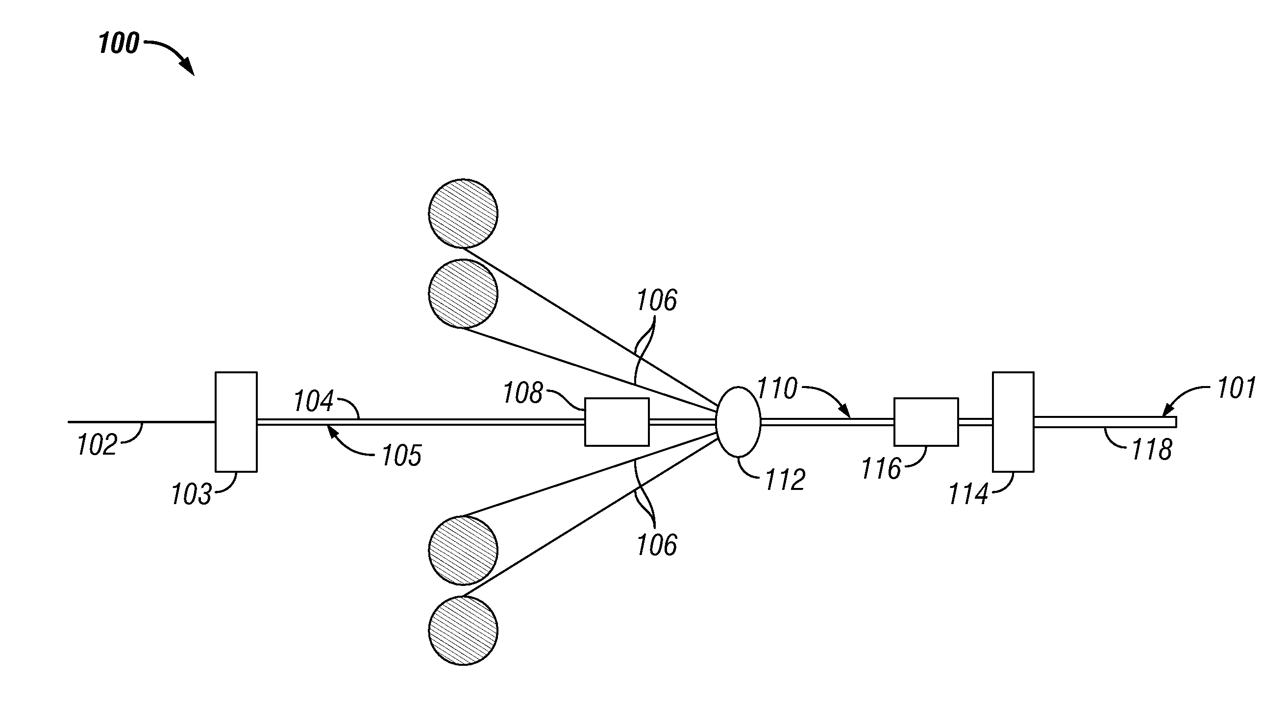
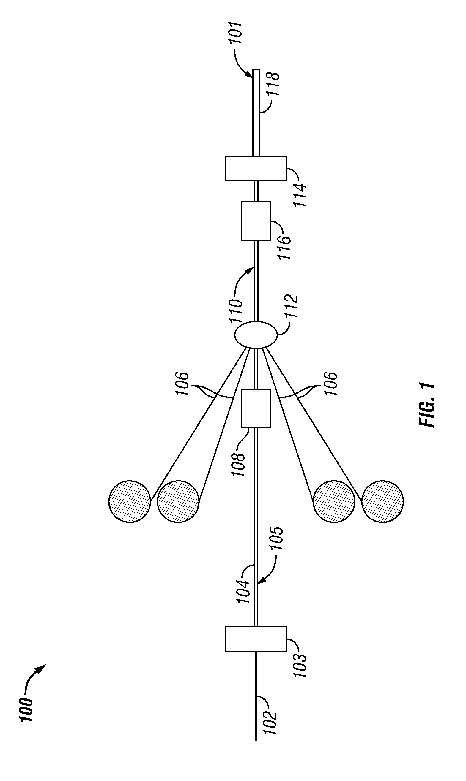
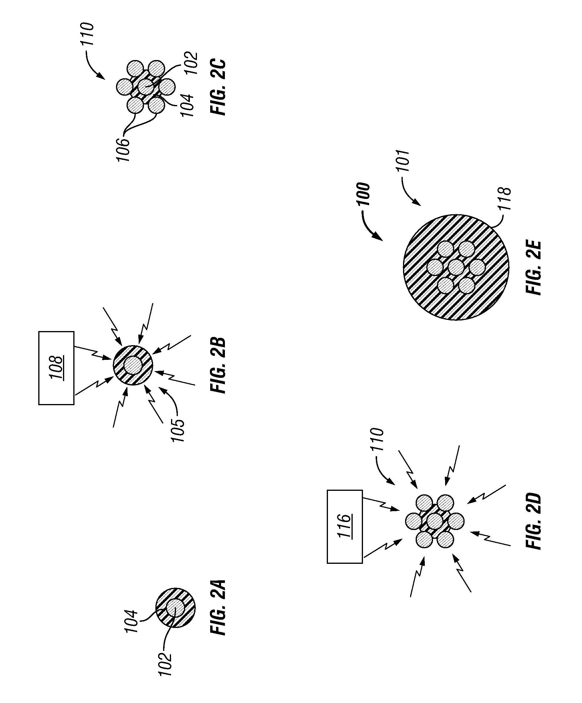
[0035]Referring now to FIGS. 1 and 2a-2e, a method for forming a cable 101 is indicated generally at 100. The method 100 begins by providing, for example, a central coated strand of copper 102, and extruding (by, for example, compression extruding or tube extruding through an extruder 103) a layer of polymeric insulation 104 over the central strand 102 to form a cable conductor core 105. Those skilled in the art will appreciate that the central stra...


PUM

PropertyMeasurementUnit
diameteraaaaaaaaaa
diameteraaaaaaaaaa
polymericaaaaaaaaaa

Abstract

A method of forming at least a portion of a cable comprises providing at least one conductor, extruding at least an inner layer of polymeric insulation over the at least one conductor to form a cable conductor core, embedding a plurality of conductors into the inner layer of the cable conductor core, and extruding an outer layer of polymeric insulation over the cable conductor core and the plurality of conductors and bonding the inner layer to the outer layer to form the cable and provide a contiguous bond between the inner layer, the conductors, and the outer layer, wherein embedding comprises heating a one of the inner layer and the conductors prior to embedding the conductors into the inner layer.

Description

CROSS-REFERENCE TO RELATED APPLICATION[0001]This application is entitled to the benefit of, and claims priority to, provisional patent application U.S. 60 / 954,156 filed Aug. 6, 2007, the entire disclosure of which is incorporated herein by reference.BACKGROUND OF THE INVENTION[0002]The statements in this section merely provide background information related to the present disclosure and may not constitute prior art. Embodiments of the present invention relates generally to wellbore cables.[0003]In high-pressure wells, wireline is run through one or several lengths of piping packed with grease to seal the gas pressure in the well while allowing the wireline to travel in and out of the well. Insulated stranded conductors typically consist of several wires (typically copper) cabled at a lay angle around a central wire, with one or more layers of polymeric insulation extruded over the bundled strands. The insulation is not able to penetrate into the spaces between the conductor strands....

Claims


Application Information

Patent Timeline
Patent Type & Authority Patents(United States)
IPC IPC(8): H01R43/00
CPCH01B13/016H01B13/145Y10T29/49123Y10T29/49117Y10T29/49162
Inventor VARKEY, JOSEPH
Owner SCHLUMBERGER TECH CORP
Why Eureka
Try Eureka