Two-piece end-effectors for robotic surgical tools

a robotic surgical tool and end-effector technology, applied in the field of robotic surgical tools, can solve the problems of large cutting edges, overexposed cutting edges of blades, and large cutting edges of drive hubs

Active Publication Date: 2011-05-03
INTUITIVE SURGICAL OPERATIONS INC
View PDF41 Cites 838 Cited by
  • Summary
  • Abstract
  • Description
  • Claims
  • Application Information

AI Technical Summary

Problems solved by technology

If the drive hub and scissor blade are manufactured together out of a one piece design, the drive hub may interfere with the sharpening / honing and stropping of a scissors blade.
Opening the blades to an angle greater than 30 degrees may expose large sections of the cutting edges, which may be undesirable in the limited space of a body cavity.
If no open stop is provided to scissors, the cutting edges of the blades may become overexposed, and if the robotic surgical tool is inadvertently moved, the overexposed cutting edges may accidentally cut tissue within a surgical site.
If no close stop is provided and the blades are closed to far to over expose a cutting edge, there is greater risk of inadvertent tissue damage within the surgical site.
However due to the brittle nature of tungsten carbide, it may not be the ideal material to form a driving element.
Furthermore, hard materials such as tungsten carbide are more difficult to stamp form into complex shapes.
Surgical sites are highly saline which may lead to faster corrosion of metals.
A metal alloy chosen with these properties may be too brittle to properly function as a drive element.
This may cause unnecessary burning at the entry port.
Furthermore, the current may be passed along the instrument 400 to the telesurgical system in general and may be damaging to sensitive electronics, e.g., forming part of the endoscope and viewer arrangement.

Method used


Image

  • Two-piece end-effectors for robotic surgical tools
  • Two-piece end-effectors for robotic surgical tools
  • Two-piece end-effectors for robotic surgical tools

Examples


Embodiment Construction

[0034]This detailed description describes embodiments that are illustrative of the invention, and so is explanatory and not limiting. The invention is limited only by patented claims. In the drawings, some elements have been omitted so as to more clearly show the embodiments of the invention. Like element numbers in the different drawings are associated with the same or similar elements but may have a different configuration.

INTRODUCTION

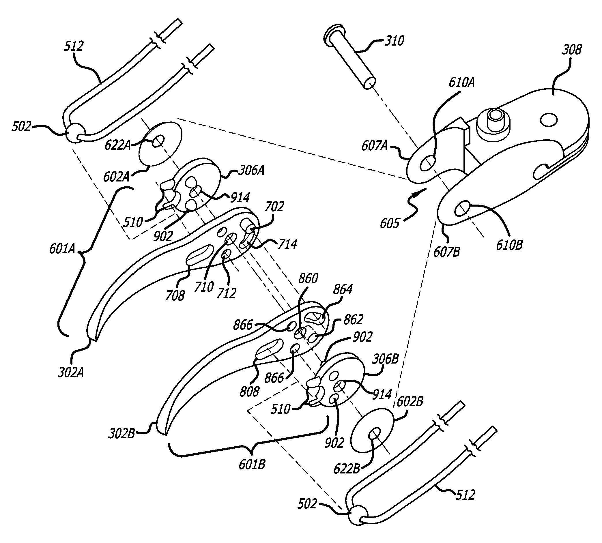
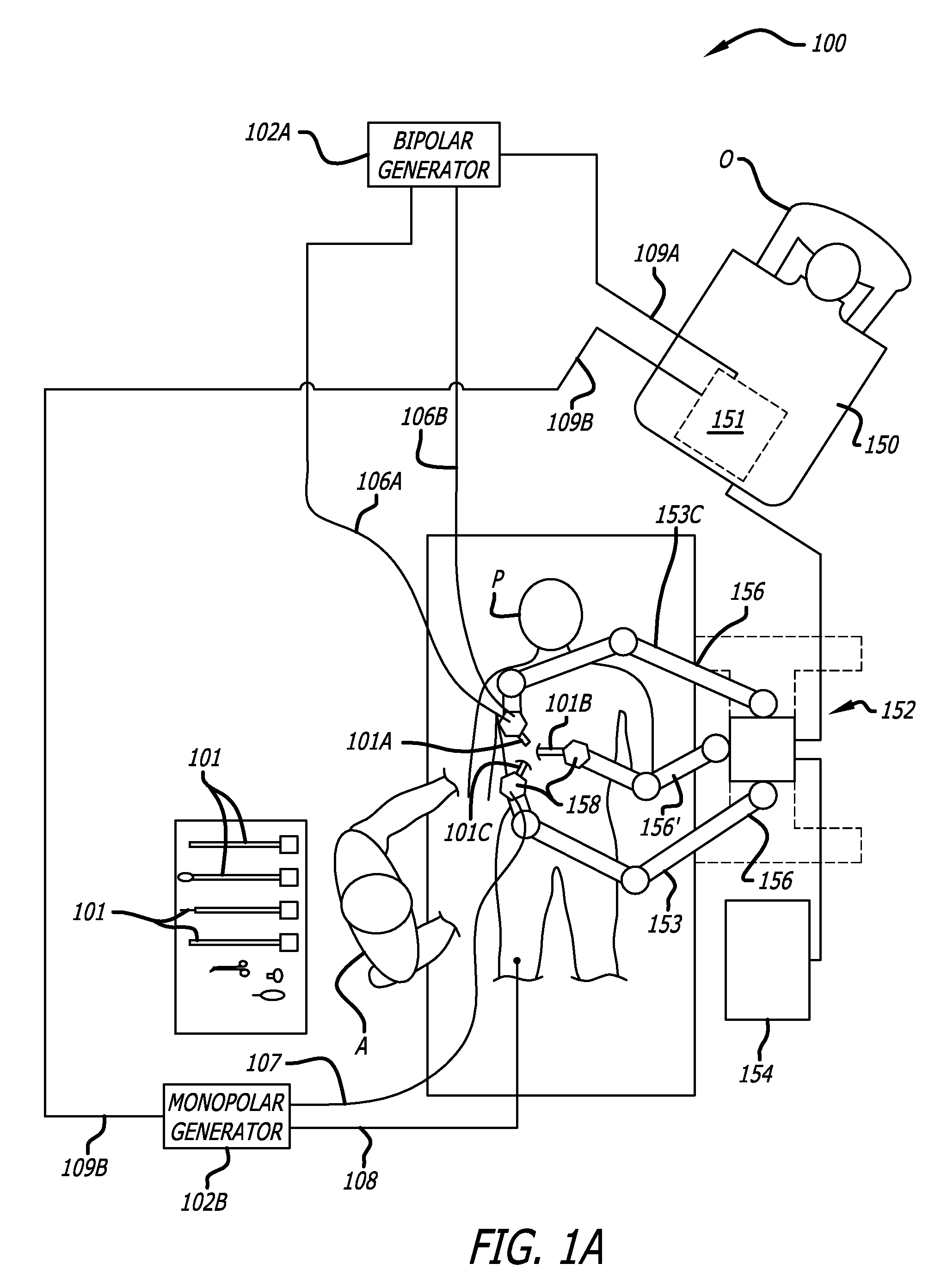
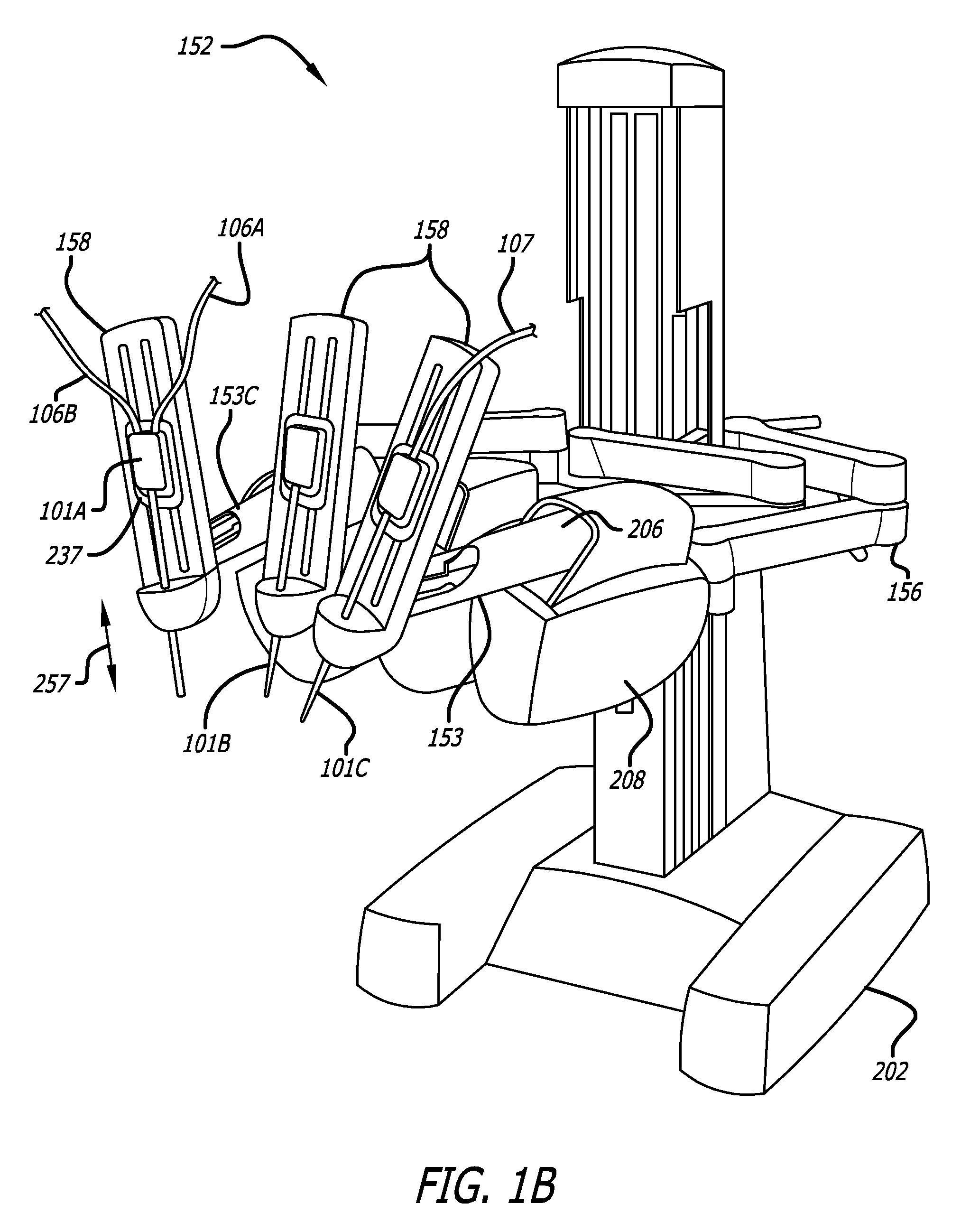
[0035]The embodiments of the invention include an apparatus and system as well as method of assembly of robotic surgical instruments or tools used in robotic surgical systems. The instruments of the present invention are capable of treating tissue while cutting or shearing treated tissue. The electrosurgical treatment may further reduce bleeding of tissue by cauterizing tissue and coagulating blood. The invention incorporates innovations to reduce the cost of manufacture of end effectors and thereby reduce problems associated with corrosion and dull ...


PUM

PropertyMeasurementUnit
angleaaaaaaaaaa
angleaaaaaaaaaa
poweraaaaaaaaaa

Abstract

In one embodiment of the invention, a robotic surgical tool having opposing jaws, the working element of the robotic surgical tool is made of a different material from the drive element of the robotic surgical tool. The two elements may be manufactured independently and assembled together at a later stage. The material comprising each element may thus have properties more appropriate to the function each element plays in the robotic surgical tool. For example, the metal selected to comprise the blade of a surgical scissor may be corrosion resistant and capable of being sharpened to a high degree.

Description

CROSS REFERENCES TO RELATED APPLICATIONS[0001]This non-provisional United States (US) patent application claims the benefit of U.S. provisional patent application No. 60 / 866,146 entitled TWO-PIECE JAW FOR SURGICAL INSTRUMENTS, filed by Matthew Williams on Nov. 16, 2006, the full disclosure of which is incorporated herein by reference.FIELD[0002]The embodiments of the invention generally relate to robotic surgical instruments.BACKGROUND[0003]The manufacture of both curved and straight scissors has been a persistent problem in robotic surgical tools. Two design considerations for the manufacture of robotic surgical scissors are performance and corrosion.[0004]The ability to cut delicate and tough tissue in a human body is limited because the force available to the robotic surgical scissors jaw blades is limited. For most robotically assisted surgery, small scissors are used because the surgical instruments must pass though small ports into a patents body. The robotic surgical scissors...

Claims


Application Information

Patent Timeline
Patent Type & Authority Patents(United States)
IPC IPC(8): A61B17/00
CPCA61B19/2203A61B17/3201Y10T29/49826A61B19/5212A61B2017/00526A61B2017/00836A61B2017/2929A61B2018/146A61B2019/2223A61B2019/2234A61B2019/2242A61B2019/2246A61B2019/305A61B2017/00477A61B18/1442A61B2034/715A61B90/361A61B34/30A61B34/37A61B2034/305A61B2090/035A61B34/71
Inventor WILLIAMS, MATTHEW REAGAN
Owner INTUITIVE SURGICAL OPERATIONS INC
Why Eureka
Try Eureka