Method and installation for processing printed products during conveyance

a technology for installing and processing printed products, which is applied in the direction of printing, article feeders, article delivery, etc., can solve the problems of long production losses, unfavorable movement of products lying on saddle-shaped supports, and high cost of equipping all saddle-shaped supports correspondingly, so as to achieve more independence of two circuits from on

Inactive Publication Date: 2011-05-10
FERAG AG
View PDF13 Cites 0 Cited by
  • Summary
  • Abstract
  • Description
  • Claims
  • Application Information

AI Technical Summary

Benefits of technology

[0008]It is the objective of the invention to create a method and an installation for processing printed products between a tool and a counter-tool during their conveyance on saddle-shaped supports, wherein, with the installation according to the invention it shall be possible to avoid the above mentioned disadvantages of known methods and installations serving the same purpose. The installation according to the invention shall therefore in particular make it possible, that the circuit of the saddle-shaped supports shall remain freely selectable, also in the processing zones, and to the greatest possible extent independent of the processing, that nonetheless the saddle-shaped supports do not have to be equipped either with tools or with counter-tools and that despite this it is possible to ensure in a simple manner, that the printed products to be processed are neither deformed nor damaged by undesirable relative movements.
[0010]The distal ends of the counter-tools moving through the saddle-shaped supports take over the carrying and guiding of the printed products to be processed to such an extent, that a relative movement between the saddle-shaped support and the counter-tool allocated to it can act on the printed product neither by deforming nor by damaging it. Because in this way, the relative movements between the saddle-shaped supports and the printed products to be processed become harmless and therefore can be tolerated, it becomes possible to design the circuit of the saddle-shaped supports and the circuit of the counter-tools such that also in the processing zone they have not the same directions and changing distances between one another, which results in significantly more independence of the two circuits from one another.

Problems solved by technology

Only in this manner there are no relative movements between tool and counter-tool and between tools and saddle-shaped support during the processing, which relative movements may undesirably deform or damage the products lying on the saddle-shaped supports.
On the other hand, however, it is very expensive to equip all saddle-shaped supports correspondingly, this in particular in the case of systems, in which the printed products are conveyed over relatively long stretches on saddle-shaped supports arranged tightly behind one another and are to be processed in various manners.
If the tools or the saddle-shaped supports equipped with the tools respectively also have to be correspondingly adjusted for enabling processing of different printed products, production changes are associated with a lot of work and as a result of this with lengthy production losses, which may well represent a further disadvantage.
The circuit of the tools and the circuit of the saddle-shaped supports are adapted to one another in the processing zone in such a manner, that there are undesirable relative movements neither between tools and counter-tools nor between tools and saddle-shaped supports.
This, however, leads to constraints regarding space, which may be serious and undesirable in particular for cases, in which different processing operations are to be carried out in successive processing zones.

Method used


Image

  • Method and installation for processing printed products during conveyance
  • Method and installation for processing printed products during conveyance
  • Method and installation for processing printed products during conveyance

Examples


Embodiment Construction

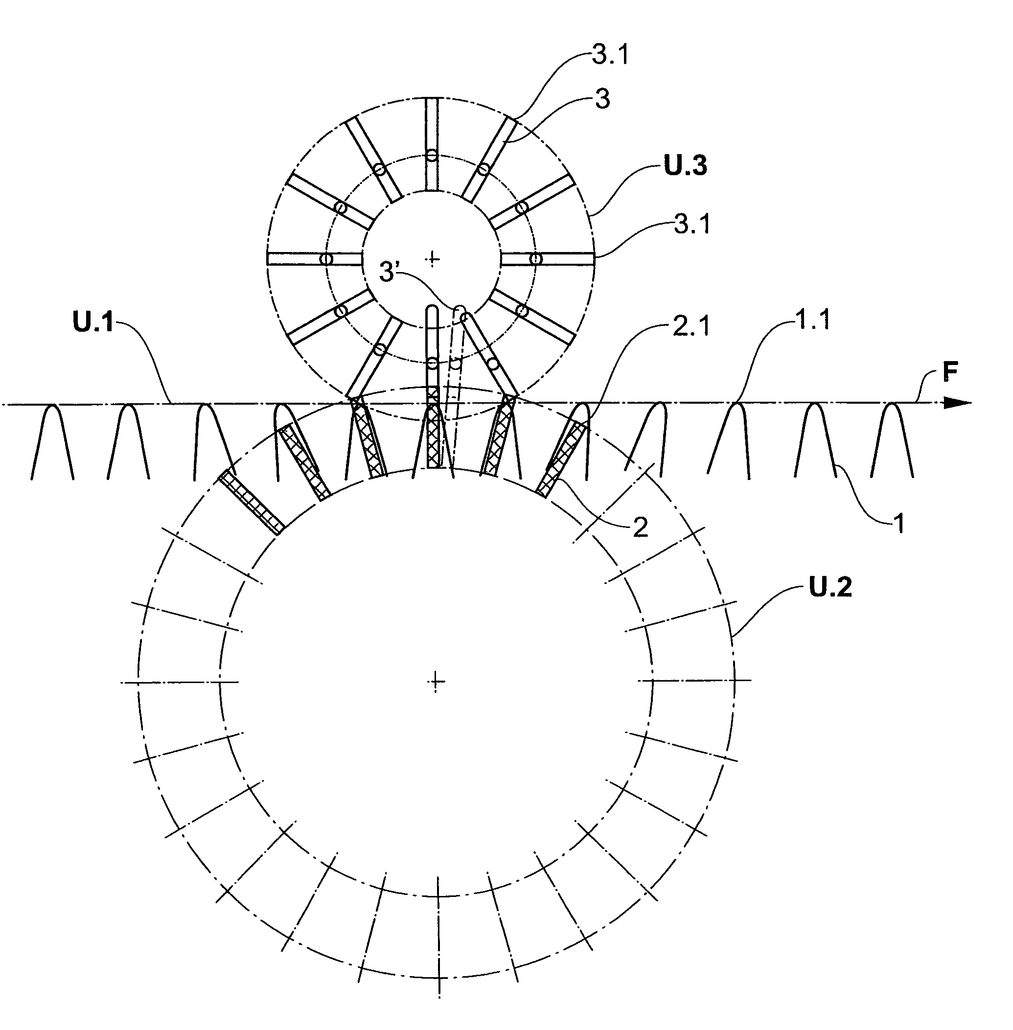
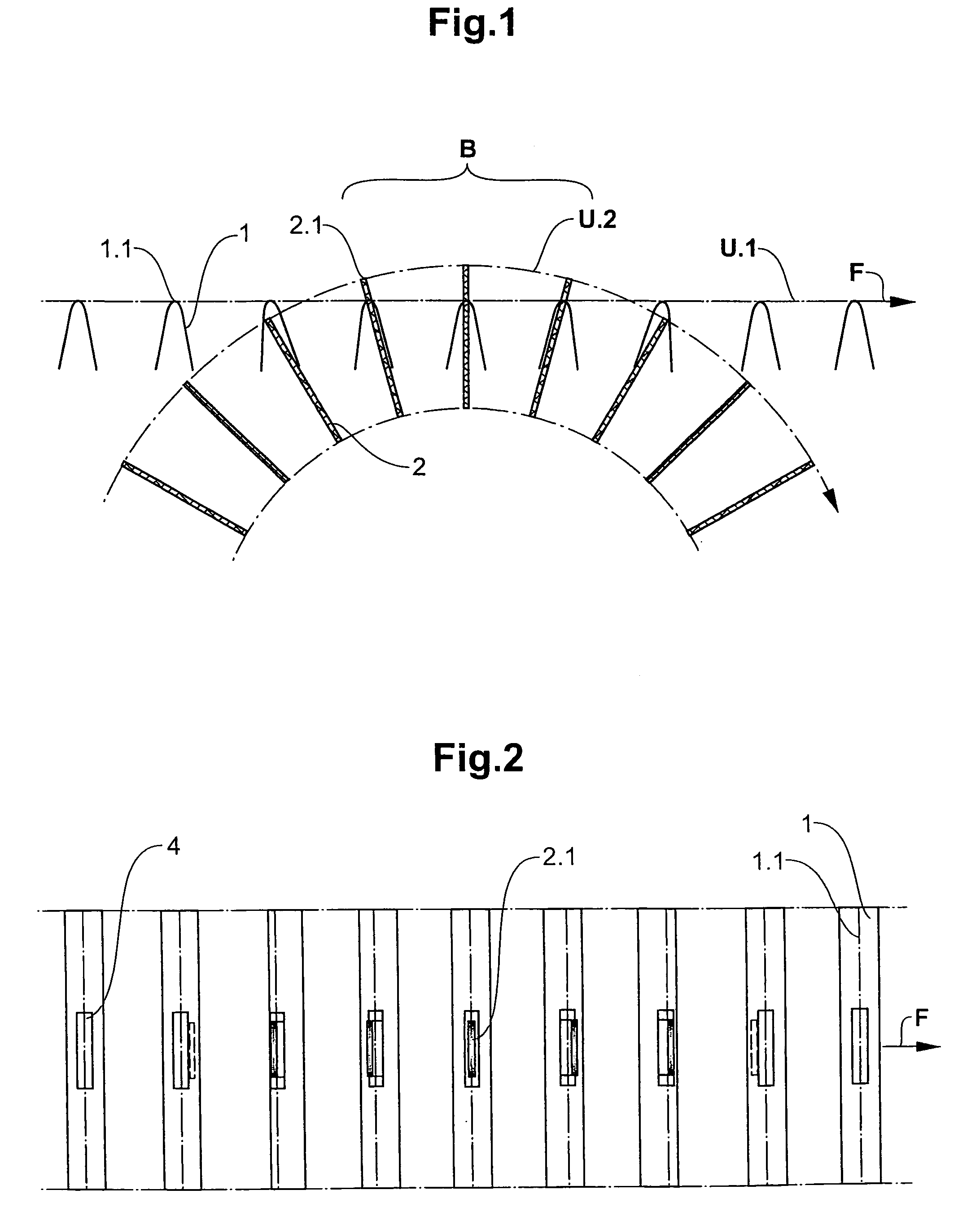
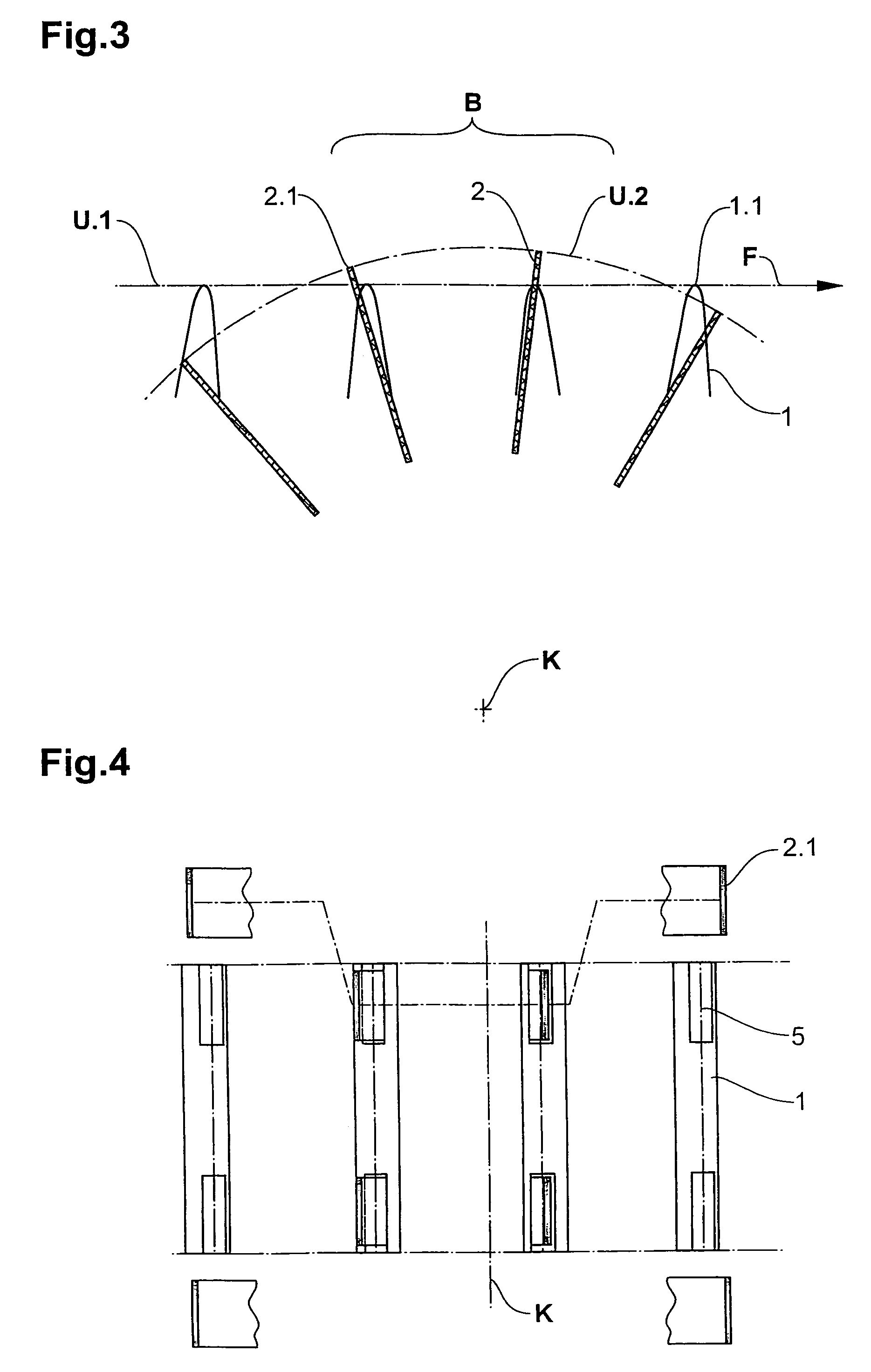
[0019]FIGS. 1 and 2 illustrate the principle of a first, preferred embodiment of method and installation according to the invention, wherein only a part of the saddle-shaped supports 1 and of the counter-tools 2 as well as partial zones of the circuit U.1 of the saddle lines 1.1 of the saddle-shaped supports 1 and of the circuit U.2 of the distal ends 2.1 of the counter-tools are depicted. FIG. 1 illustrates the installation viewed from the side, i.e. with a direction of view essentially parallel to the saddle lines 1.1 of the saddle-shaped supports 1, FIG. 2 viewed from above, i.e. with a direction of view on to the saddle lines of the saddle-shaped supports 1.

[0020]The circuits U.1 and U.2 intersect at the entrance to the processing zone B and at the exit of the processing zone B, wherein the circuit U.2 extends above the track U.1 in the processing zone B. This means, that the distal ends 2.1 of the counter-tools 2 are positioned above the saddle lines 1.1 of the saddle-shaped su...


PUM

PropertyMeasurementUnit
areaaaaaaaaaaa
processingaaaaaaaaaa
circumferenceaaaaaaaaaa

Abstract

Printed products produced by assembling on saddle-shaped supports are conveyed onwards lying on the supports and during this conveyance are processed in the area of their fold line between a tool acting from outside and a counter-tool acting from inside, i.e., from the supported side. For being processed, the printed products are lifted off from the saddle line of the supports by the counter-tools, such that a relative movement between the saddle-shaped support and the counter-tool does not deform or damage the printed products. Through this measure it becomes possible to design the circuit of the supports and the circuit of the counter-tools largely independent of one another. The supports or their saddle lines respectively, for example, are able to move through the processing zone in a straight line, while the distal ends of the counter tools circulate on a round circuit.

Description

FIELD OF THE INVENTION[0001]The invention is related to a method and an installation for processing printed products, which are conveyed essentially continuously lying on saddle-shaped supports arranged in essence transverse to the conveying direction.BACKGROUND OF THE INVENTION[0002]It is known to produce printed products by assembling folded sheets or folded partial products, wherein at successive feeding points these are placed on to saddle-shaped supports being conveyed continuously and usually aligned transverse to the conveying direction, such, that the inner fold line of the first folded sheet or partial product is lying on the saddle line of the support and the two folded parts are supported by the support or hang substantially freely downwards, and such, that further supplied sheets or partial products are placed on to the first sheet and on top of one another. For folding sheets or partial products in the named manner, for example, a rotating collecting drum is utilised, i...

Claims


Application Information

Patent Timeline
Patent Type & Authority Patents(United States)
IPC IPC(8): B65H37/04
CPCB42B4/02B65H5/32B42C1/12B65H2301/3221
Inventor MULLER, ERWIN
Owner FERAG AG
Why Eureka
Try Eureka