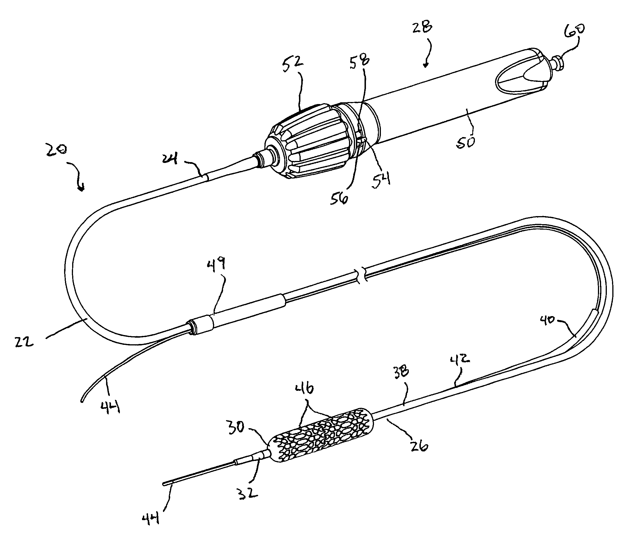
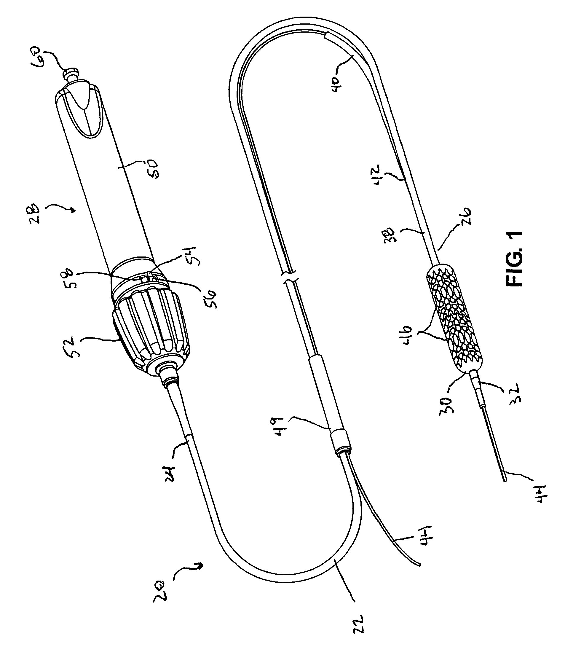
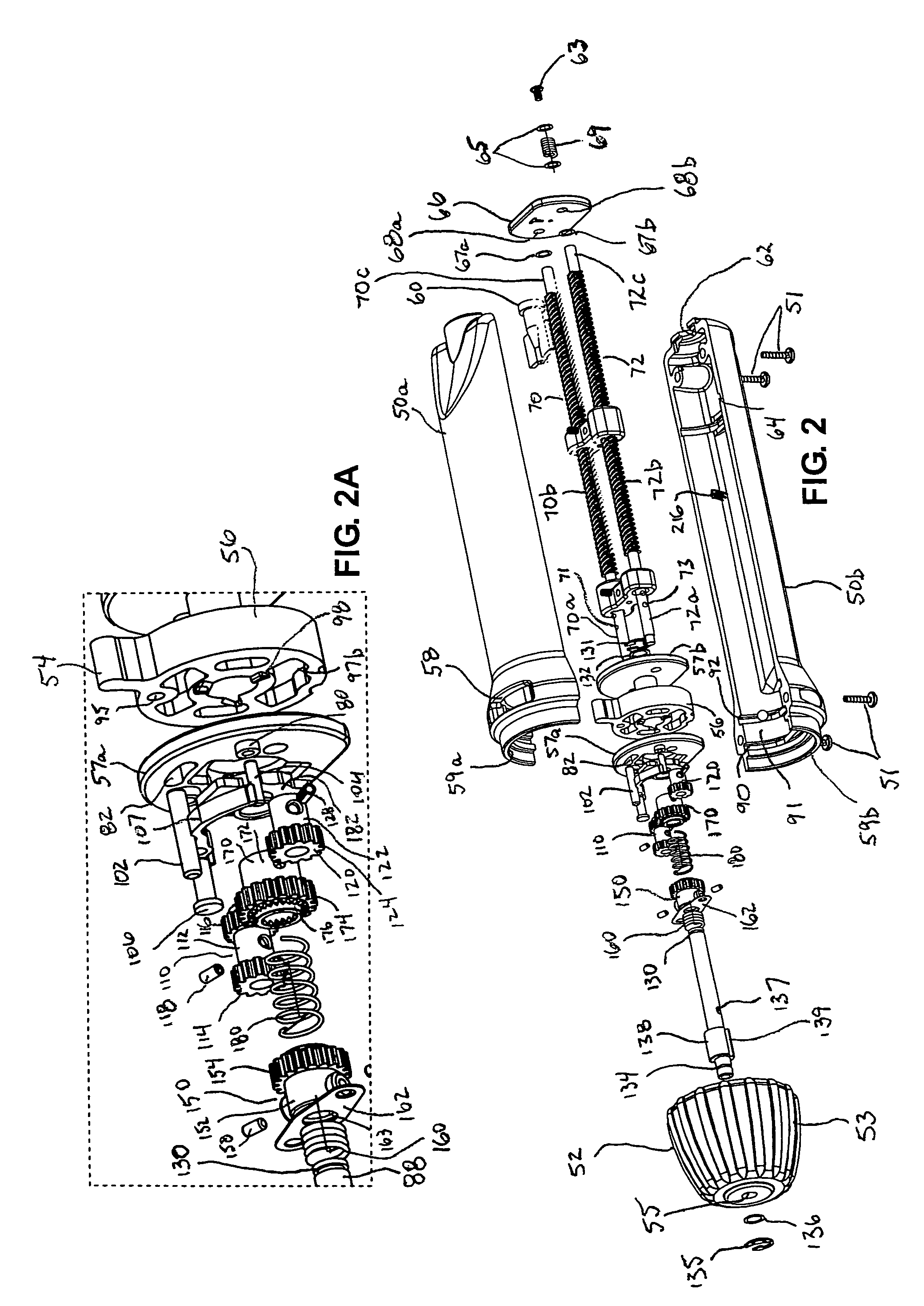
[0017]In other embodiments, a system of rollers and actuator knob engagement surfaces provides the translation of rotation of the actuator knob to rotational movement of the one or more lead screws. Each roller is selectively engageable with one or more engagement surfaces of the actuator knob such that rotation of the actuator knob causes the roller to rotate. Each roller may be directly or indirectly connected to a respective lead screw to cause the lead screw to rotate as the roller rotates. In a preferred embodiment, the rotation direction of a roller may be different dependent upon the actuator knob engagement surface the roller is engaged with, thereby providing the capability to reverse the rotation of the lead screw for a given rotation direction of the actuator knob.
[0021]The handle may be provided with an optional lock-out mechanism that selectively prevents the actuator knob from rotating one or more of the lead screws when the selector member is in a predetermined position corresponding to a predetermined mode of operation. The preferred lock-out mechanism includes a rocker arm having a pawl formed on one end thereof, the pawl being selectively engageable with a gear interposed between the actuator knob and a lead screw. A pin selectively engages the rocker arm to cause the pawl to engage or disengage from the gear. When the pawl is engaged, the gear is only allowed to rotate in an allowed direction, but is prevented from rotating in the opposite direction. The lock-out mechanism may be used, for example, to prevent advancement of the outer sheath when the actuator is in a mode of operation corresponding with inflation of the balloon at the distal end of the catheter. Other uses of the lock-out mechanism are also possible.
[0022]The handle may also be provided with an optional clutch mechanism that causes the actuator knob to become disengaged from the drive shaft when a predetermined amount of torque is applied to the actuator knob. The clutch mechanism includes a first clutch plate attached to the actuator knob, and a second clutch plate attached to the drive shaft. The drive shaft, in turn, is selectively coupled to the one or more lead screws. Under normal operation, with the clutch engaged, rotation of the actuator knob causes rotation of the one or more lead screws (when engaged by the selector). However, the clutch plates are constructed such that, when the amount of torque applied to the actuator knob reaches a predetermined limit, the clutch plates disengage, thereby preventing the actuator knob from causing rotation of any of the one or more lead screws. Selected clutch disengagement may be obtained by appropriate construction of the clutch plate teeth, by selection of materials, by selection of a clutch spring of appropriate size and spring constant, or by other methods known in the art. The clutch mechanism may be useful, for example, to prevent over-resetting the outer sheath when the sheath is being advanced distally.
[0024]Alternatively, the inflation lumen disable mechanism may include a clamp that is applied to a portion of tubing or other member placed in the inflation lumen line. Either mechanism may be used to substantially or completely prevent or divert fluid flow away from or out of the inflation lumen.
[0025]The handle may also be provided with a limiting mechanism that limits the amount of axial movement of one or more of the threaded engagement members on the respective lead screws. For example, a tab may be fixed to a surface of an engagement member such that it engages a detent formed on an internal surface of the handle housing when the engagement member reaches a predetermined point of travel along the lead screw. The detent engages the tab, preventing any further axial movement of the engagement member. In some embodiments, the position of the detent within the handle housing is adjustable, thereby providing the user with the capability of adjusting the length of allowable travel of the engagement member.
[0026]Additional features that optionally may be included on or with the handle include the use of one or more variable pitch lead screws to provide the ability to speed up or slow down the axial movement of the engagement member on the lead screw for a given rotation speed. Thus, certain modes of operation may be performed more quickly, while other modes of operation (e.g., those that require fine adjustment) may be performed more slowly. Yet another additional option feature is the provision of a motor either internally or externally of the handle, the motor being adapted to automate or semi-automate the handle operation. The motor may optionally be programmed to perform certain predetermined modes of operation as desired.


