Antireflective structure and antireflective molded body

a technology of anti-reflective structure and molded body, which is applied in the direction of optics, thin material handling, instruments, etc., can solve the problems of deteriorating anti-reflectivity, scratching the surface, and difficulty in viewing the various meters of the display, so as to improve the anti-reflectivity of electromagnetic waves and prevent damage to the head end parts

Inactive Publication Date: 2011-05-10
NISSAN MOTOR CO LTD
View PDF4 Cites 8 Cited by
  • Summary
  • Abstract
  • Description
  • Claims
  • Application Information

AI Technical Summary

Benefits of technology

[0016]It is an object of the present invention to provide an antireflective structure capable of improving antireflectivity of an electromagnetic wave and preventing damage to a head end part of each of fine protrusions of irregularities by optimizing shape of the head end part In other words, the object of the present invention is to provide the antireflective structure having both antireflectivity and scratchproof.

Problems solved by technology

In this case, however, the scenery outside the vehicle is imaged in through a front window or a side window to the meter front cover, as the case may be, making it difficult to view the various meters of the display.
However, JP2002267815 may cause scratches to the surface of the antireflective structure, as the case may be, deteriorating the antireflectivity.

Method used


Image

  • Antireflective structure and antireflective molded body
  • Antireflective structure and antireflective molded body
  • Antireflective structure and antireflective molded body

Examples


first embodiment

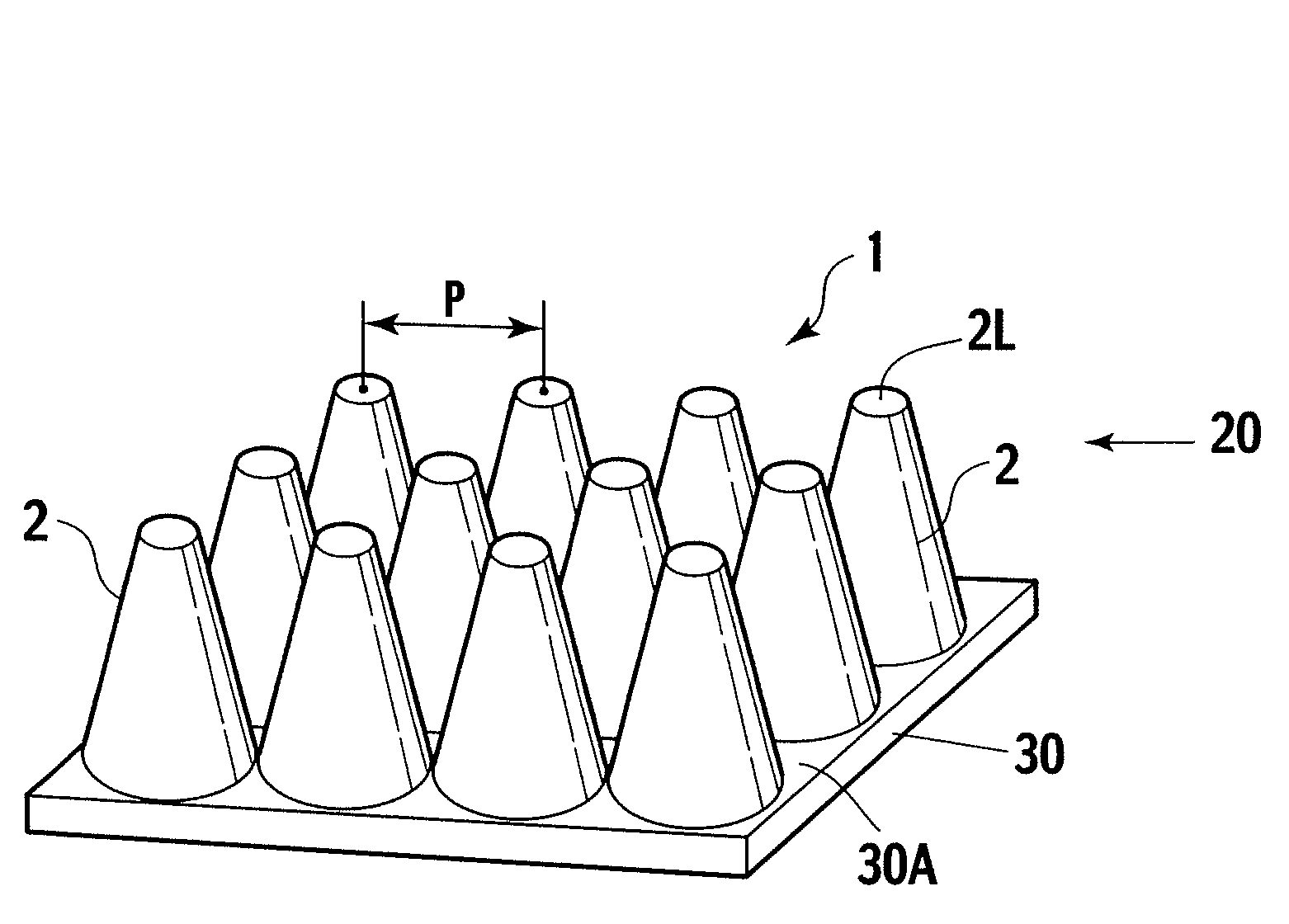
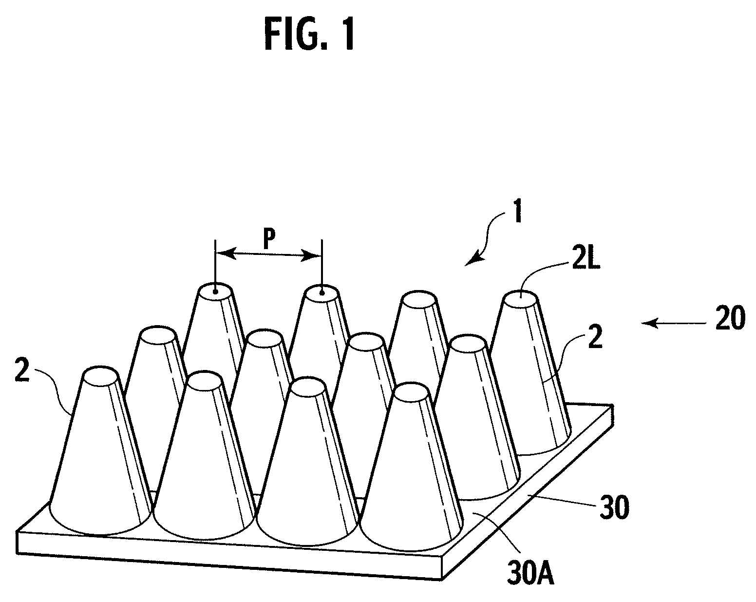
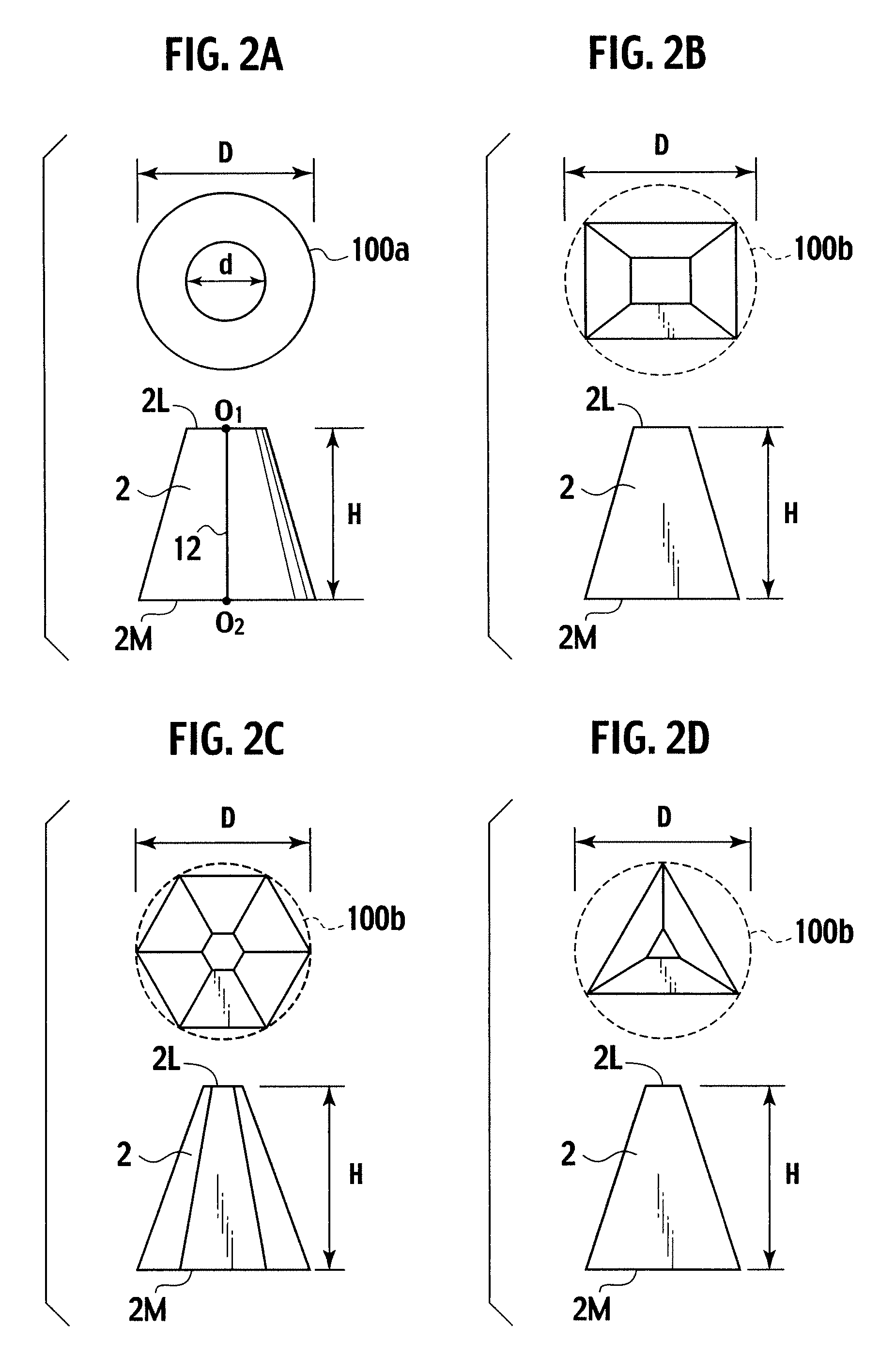
[0036]FIG. 1 shows an antireflective structure 1, according to a first embodiment of the present invention. In the antireflective structure 1 of the present invention, a myriad of fine protrusions 2 each having a flat head end part 2L and shaped substantially into a truncated cone or a truncated pyramid (truncated cone in FIG. 1 according to the first embodiment) are arranged such that a pitch P of the fine protrusion 2 is smaller than a wavelength λ of an incident electromagnetic wave. The fine protrusions 20 form a fine structure layer 20. FIG. 1 also shows a flat layer 30 having a surface 30A on which the fine protrusions 2 are disposed. Hereinabove, a base face 2M of the fine protrusion 2 is smaller in size than the wavelength λ of the incident electromagnetic wave. More specifically, in the case of the truncated cone, a diameter D of a circle 100a of the base face 2M of the fine protrusion 2 is smaller than the wavelength λ of the incident electromagnetic wave (see FIG. 2A). Li...

example 1

[0120]A mold developed by a commercial electron beam drawing device was used. The mold was heated to 170° C. Then, 10 MPa of a pressure was applied to first and second faces 201A, 201B (both faces) of a polycarbonate (“PC” for short) substrate 201 for 1 hr, followed by cooling at less than or equal to 70° C., to thereby prepare an antireflective molded body 200 having both faces each formed with the antireflective structure 1 where the fine protrusions 2 are arranged in a hexagonal packed structure (pitch P: 1000 nm), as shown in Table 1. Each of the fine protrusions 2 has the following specifications:

[0121]

1) Overall configurationTruncated cone2) Diameter D of base face 2M:1000 nm 3) Diameter d of head end face 2L:250 nm4) Height H:750 nm

[0122]Then, the thus prepared antireflective molded body 200 was subjected to an irradiation of an infrared ray having a wavelength of 2000 nm, so as to measure reflectivity at an incident angle of 0 degree and a measurement angle of 0 degree, to t...

example 2

[0127]A mold developed by a like electron beam drawing device was used. Operations like those of the example 1 were repeated, to thereby prepare an antireflective molded body 200 including a polymethyl methacrylate (“PMMC” for short) substrate 201 having first and second faces 201A, 201B each formed with the antireflective structure 1 where the fine protrusions 2 are arranged in a hexagonal packed structure (pitch P: 300 nm), as shown in Table 1. Each of the fine protrusions 2 has the following specifications:

[0128]

1) Overall configurationTruncated cone2) Diameter D of base face 2M:300 nm3) Diameter d of head end face 2L: 45 nm4) Height H:220 nm

[0129]Then, the thus prepared antireflective molded body 200 was subjected to an irradiation of a visible light having a wavelength of 555 nm, so as to measure reflectivity at an incident angle of 0 degree and a measurement angle of 0 degree, to thereby evaluate antireflectivity.

[0130]Then, the scratchproof test was implemented on a surface o...


PUM


Abstract

An antireflective structure includes: a flat layer having a surface; a fine structure layer including: fine protrusions each including: a head end part, and a base face which is at least one of: a circular base face of a truncated cone, the circular base face having diameter of circle, and a polygonal base face of a truncated pyramid, the polygonal base face having diameter of circumscribing circle of polygonal base face, the fine protrusions being arranged on the surface of the flat layer to define a pitch, wherein, with first reflective face formed in head end part of each of the fine protrusions, and second reflective face formed between fine protrusions on the surface of flat layer: each of the diameter of the circle and the diameter of the circumscribing circle is smaller than wavelength of incident electromagnetic wave, and the pitch is smaller than wavelength of incident electromagnetic wave.

Description

BACKGROUND OF THE INVENTION[0001]1. Field of the Invention[0002]The present invention relates to an antireflective structure which is excellent in electromagnetic wave antireflectivity as well as scratchproof.[0003]The present invention also relates to an antireflective molded body which includes the above antireflective structure and is preferably used as a non-reflective panel for bodies, various meters, displays and the like of vehicles (automobiles), ships, aircrafts and the like.[0004]2. Description of the Related Art[0005]In such fields as aircrafts, automobiles, ships and the like, antireflection of electromagnetic wave is necessary for such applications as: i) stealth technology not viewed on radar, ii) an IR measurement camera, a meter cover, a liquid crystal display which are used for measuring vehicle-to-vehicle distance, and the like.[0006]For example, a driver's seat of an automobile has a meter front cover which is embedded in a front face of a display where various me...

Claims


Application Information

Patent Timeline
Patent Type & Authority Patents(United States)
IPC IPC(8): G02B27/10
CPCG02B1/118Y10T428/24174
Inventor NOGUCHI, YUJIFUKUI, TAKAYUKI
Owner NISSAN MOTOR CO LTD
Why Eureka
Try Eureka