Anti-reflection structure with graded refractive index layer and optical apparatus including same

a refractive index layer and anti-reflection technology, applied in the field of anti-reflection structure, can solve the problems of inability to achieve sufficient mechanical strength, inability to secure physical or mechanical strength inability to wipe the surface of the minute roughness structure, etc., to achieve high mechanical strength of the surface and high anti-reflection performance

Active Publication Date: 2016-03-22
CANON KK
View PDF8 Cites 5 Cited by
  • Summary
  • Abstract
  • Description
  • Claims
  • Application Information

AI Technical Summary

Benefits of technology

[0011]The present invention provides an anti-reflection structure having a high mechanical strength of its surface and a high anti-reflection performance, and an optical element and an optical apparatus using the same.

Problems solved by technology

However, securing physical or mechanical strength of the minute roughness structure is difficult, and a surface of the minute roughness structure cannot be wiped because it has roughness.
However, in the minute roughness structure disclosed in Japanese Patent Laid-Open No. 2008-9408, since the space around the convex portions are filled with the porous layer whose refractive index is significantly low, a sufficient mechanical strength cannot be expected.
Moreover, the anti-reflection thin film disclosed in Japanese Patent Laid-Open No. 08-83581 has a sufficient mechanical strength, but does not have a sufficient anti-reflection performance.
The anti-reflection layer provided in the anti-reflection thin film has a low anti-reflection performance only capable of reducing reflection at the electrically-conductive layer, and does not have a high anti-reflection performance capable of preventing reflection at a surface of an optical element.

Method used


Image

  • Anti-reflection structure with graded refractive index layer and optical apparatus including same
  • Anti-reflection structure with graded refractive index layer and optical apparatus including same
  • Anti-reflection structure with graded refractive index layer and optical apparatus including same

Examples


embodiment 1

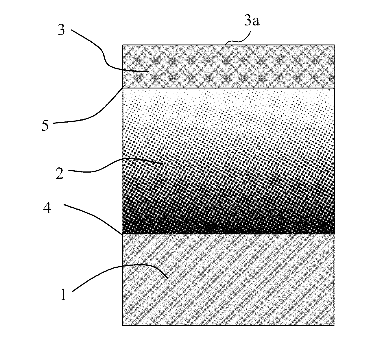
[0051]A more detailed description will be made of the anti-reflection structure of Embodiment 1 with reference to FIG. 1. The graded refractive index layer 2 and the low refractive index layer 3 are laminated on the surface of the substrate 1. The refractive index of the graded refractive index layer 2, as described above, decreases from the substrate side interface 4 toward the low refractive index layer side interface 5. The low refractive index layer 3 is a porous layer (mesoporous layer) being formed of mesoporous silica and having an even refractive index. The mesoporous silica includes a lot of minute holes in silica as shown in FIG. 14. The refractive index of the low refractive index layer 3 is decided depending on the rate (hole rate) of the minute holes occupying the mesoporous silica. A higher hole rate of the mesoporous silica provides a lower refractive index.

[0052]The graded refractive index layer 2 is a layer formed by binary vapor deposition of TiO2 and SiO2. The ref...

embodiment 2

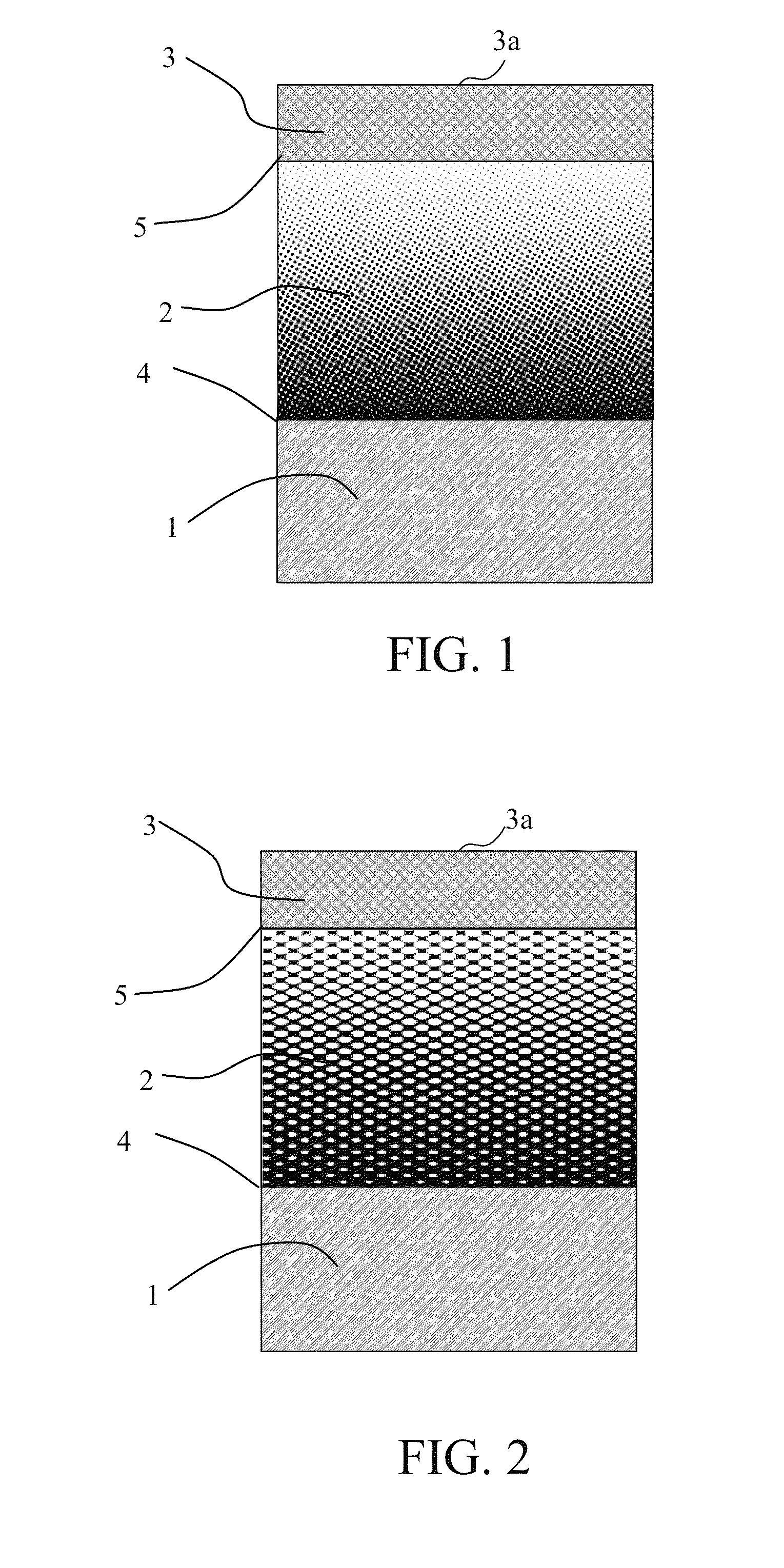
[0065]A more detailed description will be made of the anti-reflection structure of Embodiment 2 with reference to FIG. 2. The graded refractive index layer 2 and the low refractive index layer 3 are laminated on the surface of the substrate 1. The refractive index of the graded refractive index layer 2, as described above, decreases from the substrate side interface 4 toward the low refractive index layer side interface 5. As in Embodiment 1, the low refractive index layer 3 is a porous layer being formed of mesoporous silica and having an even refractive index.

[0066]The graded refractive index layer 2 is a porous layer (mesoporous layer) being formed of mesoporous SnO2 and having a structure in which a lot of minute holes are formed in SnO2. As with the mesoporous silica, a higher hole rate of the mesoporous SnO2 provides a lower refractive index. In this embodiment, as shown in FIG. 15, the hole rate in the graded refractive index layer 2 decreases as a distance to the substrate s...

embodiment 3

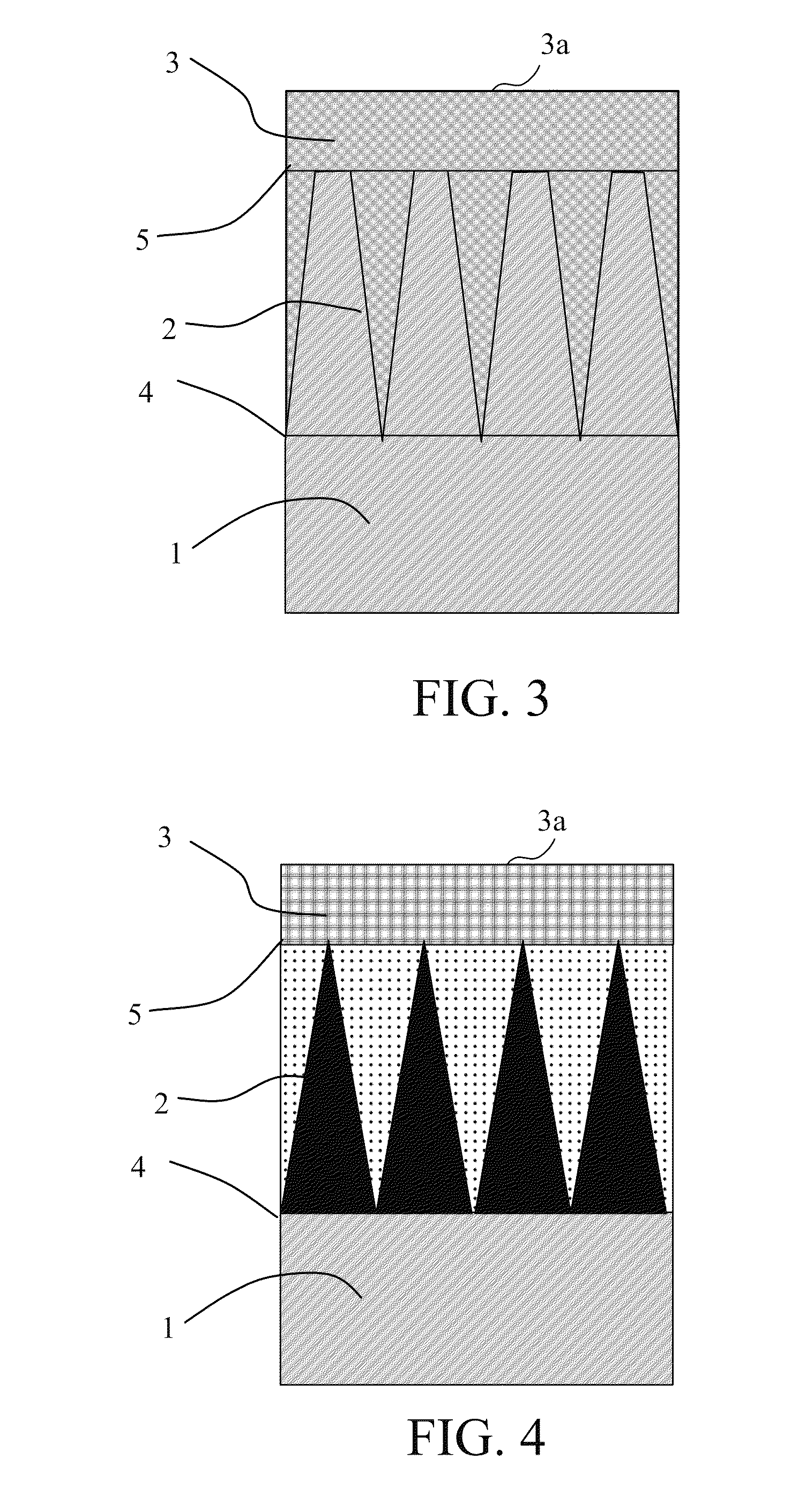
[0073]A more detailed description will be made of the anti-reflection structure of Embodiment 3 with reference to FIG. 3. The graded refractive index layer 2 and the low refractive index layer 3 are laminated on the surface of the substrate 1. The refractive index of the graded refractive index layer 2, as described above, decreases from the substrate side interface 4 toward the low refractive index layer side interface 5. As in Embodiment 1, the low refractive index layer 3 is a porous layer (mesoporous layer) being formed of mesoporous silica and having an even refractive index.

[0074]The graded refractive index layer 2 includes a base layer being formed of a same medium as that of the substrate 1 and having minute roughness (minute convex portions forming concave area therearound). A pitch (dimension) of the convex portions is about ½λ that is smaller than the using wavelength λ. Moreover, the convex portions occupy a volume of almost 100% in the graded refractive index layer 2 at...


PUM


Abstract

The anti-reflection structure includes a graded refractive index layer that is disposed on a substrate and whose refractive index decreases as a distance from the substrate increases, and a homogeneous layer that is disposed on the graded refractive index layer and whose refractive index is homogeneous. The structure satisfies a condition of nb−na>0.10 where na represents the refractive index of the homogenous layer, and nb represents a homogenous layer side effective refractive index of the graded index refractive index layer.

Description

BACKGROUND OF THE INVENTION[0001]1. Field of the Invention[0002]The present invention relates to an anti-reflection structure that is formed on an optical element as a substrate such as a lens.[0003]2. Description of the Related Art[0004]As a structure that is capable of preventing reflection of light on a surface of an optical element such as a lens and is a structure other than anti-reflection films using an interference effect obtained by a dielectric multilayer film, there is known a structure having roughness (convex and concave portions) in which a pitch of the convex portions is equal to or smaller than a wavelength of entering light. Such a structure is hereinafter referred to as a “minute roughness structure”. The minute roughness structure utilizes a property of light acting on convex portions whose pitch is equal to or smaller than a wavelength of the light as if the structure has a homogeneous effective refractive index.[0005]Such a minute roughness structure is regarded...

Claims


Application Information

Patent Timeline
Patent Type & Authority Patents(United States)
IPC IPC(8): G02B1/10G02B1/118
CPCG02B1/118B29L2011/0016
Inventor MOMOKI, KAZUHIKOMIYATA, HIROKATSUTAKAHASHI, MASAHIKOSANO, DAISUKE
Owner CANON KK
Why Eureka
Try Eureka