Electrowetting device with polymer electrode

a technology of electrodes and polymers, applied in the field of electrode electrodes, can solve the problems of reducing the focal range of the lens, inaccurate machining of the body, and reducing the contact zone with the liquid interfa

Inactive Publication Date: 2011-05-10
INVENIOS FRANCE SAS
View PDF9 Cites 10 Cited by
  • Summary
  • Abstract
  • Description
  • Claims
  • Application Information

AI Technical Summary

Problems solved by technology

However, it has been found that for such small dimensions, machining the body is inaccurate.
This inaccuracy necessitates an increase in the margins needed for certain surfaces of the body, which leads to a decrease in the zone available for contact with the liquid interface, which in turn leads to a reduced focal range of the lens.

Method used


Image

  • Electrowetting device with polymer electrode
  • Electrowetting device with polymer electrode
  • Electrowetting device with polymer electrode

Examples


Embodiment Construction

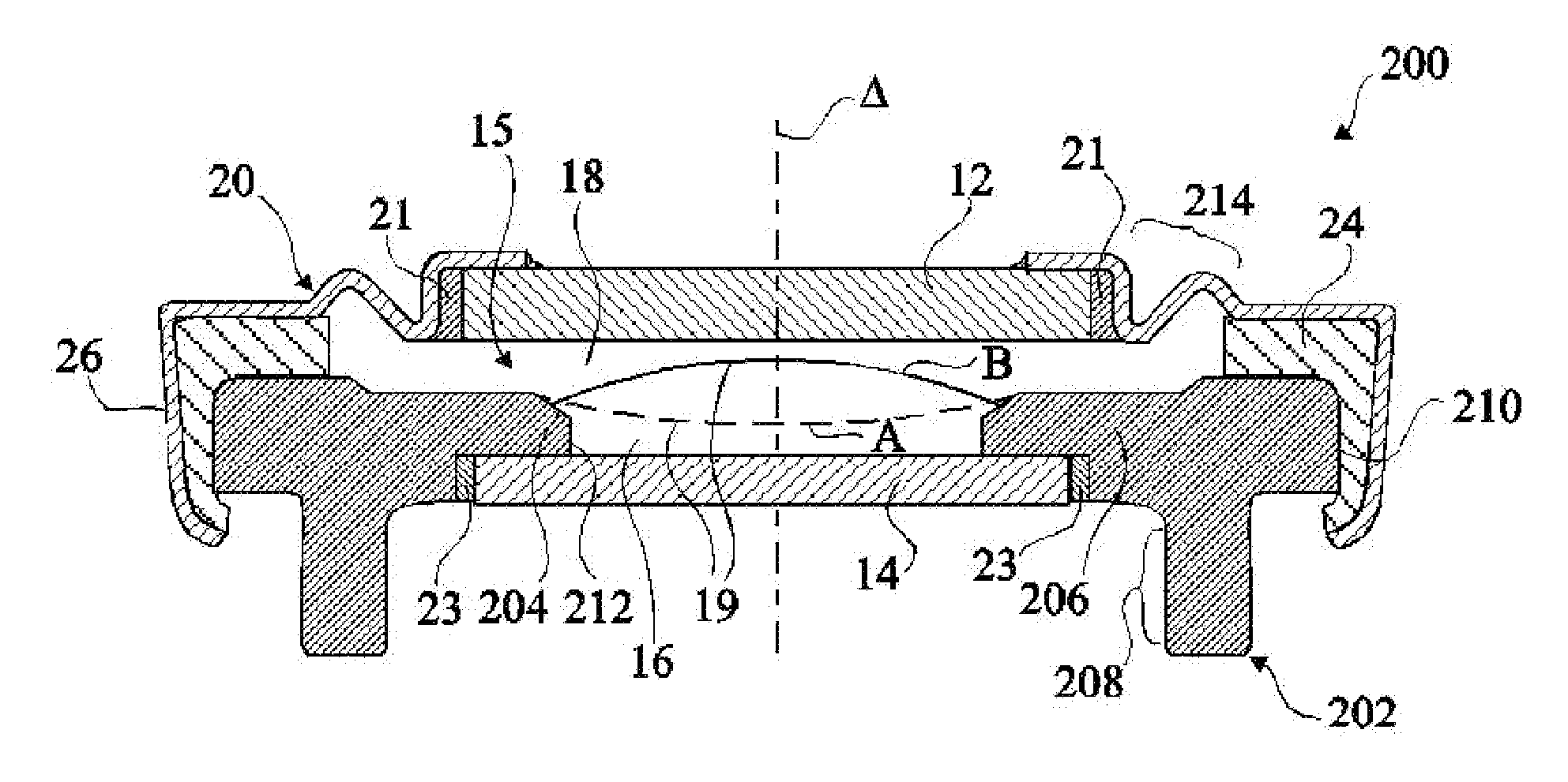
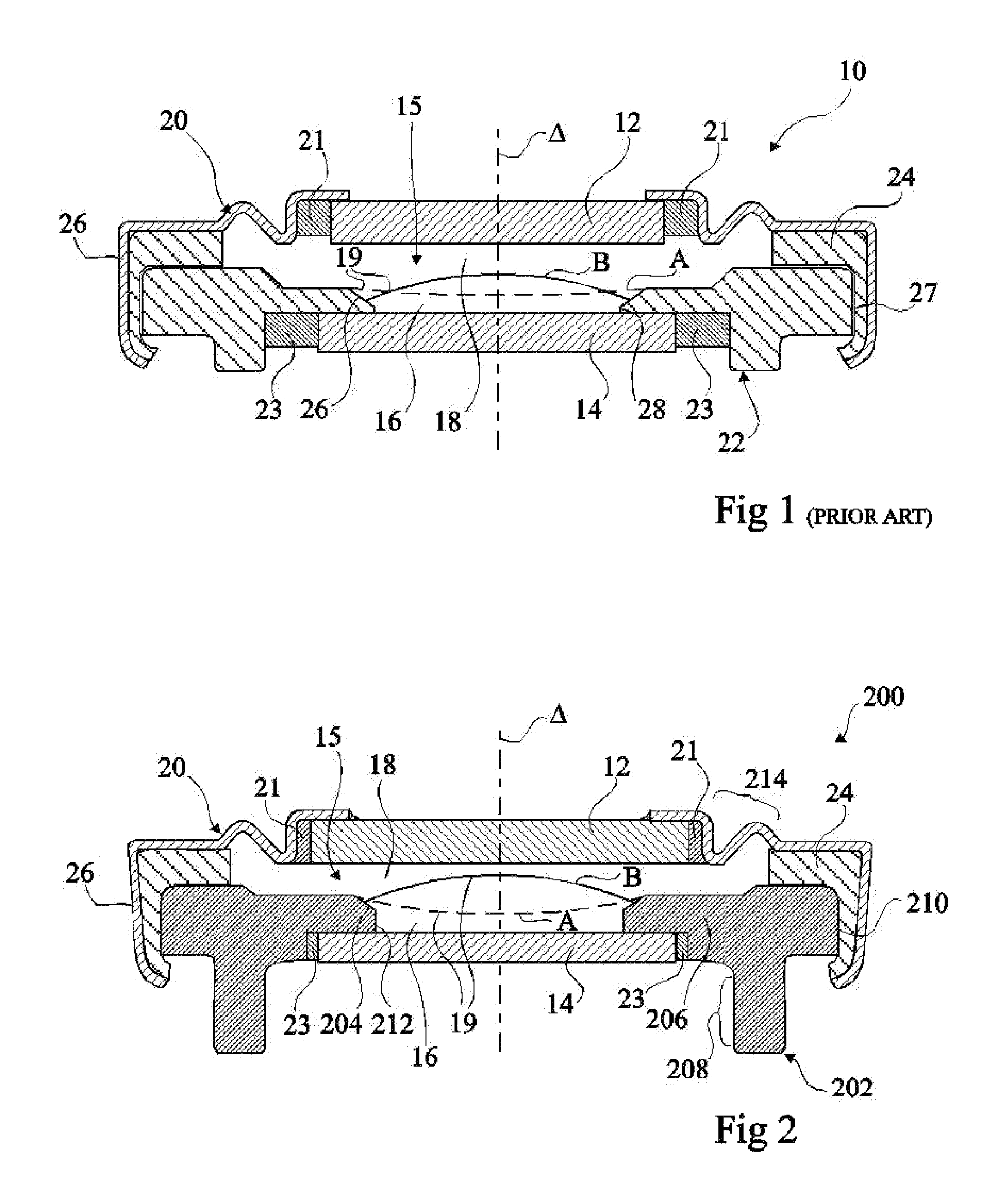
[0041]FIG. 2 is a cross-section view illustrating an example of a variable focus liquid lens 200 according to the invention. Lens 200 comprises many of the same parts as lens 10 described above, such as the transparent windows 12, 14, liquids 16, 18, cap 20, and gasket 24, and these parts will not be described again in detail. However, in lens 200, the body 22 has been replaced by a body 202.

[0042]The body 202 is molded in a conductive polymer material. The body 202 is molded to comprise a conical surface 204, which is rotationally symmetric to the optical axis Δ of the lens, and is used to center the refractive interface 19. Conical surface 204 is a bevelled surface inclined with respect to the optical axis Δ such that it forms part of a cone having its point passing through the optical axis Δ.

[0043]Body 202 further comprises a recessed region 206 for receiving window 14, and an annular foot 208, protruding from the underside of the body, which facilitates connection of the body 20...


PUM

PropertyMeasurementUnit
heightaaaaaaaaaa
thicknessaaaaaaaaaa
thicknessaaaaaaaaaa

Abstract

The invention concerns an electrowetting optical device comprising a chamber (15) comprising first and second immiscible liquids (16, 18) contacting each other at a liquid-liquid interface (19), the first liquid being an insulating liquid and the second liquid being a conducting liquid; a first electrode (20) in the contact with the second liquid; and a second electrode (202) insulated from the first and second liquids by an insulating layer, wherein the second electrode is formed of a conductive molded polymer material, wherein the curvature of said liquid-liquid interface is controllable by application of a voltage between said first and second electrodes.

Description

FIELD OF THE INVENTION[0001]The present invention relates to an electrowetting device, and in particular to an electrowetting device having at least one electrode formed of a polymer material.BACKGROUND OF THE INVENTION[0002]Electrowetting devices, and in particular electrowetting lenses, are known in the art, and generally comprise a refractive interface between first and second immiscible liquids that is movable by electrowetting.[0003]FIG. 1 represents FIG. 4 of European Patent Application EP 1662276, and illustrates a variable focus lens 10 according to one example of the prior art. Lens 10 comprises two transparent windows 12, 14, arranged in parallel and facing each other, and delimiting, in part, an internal volume 15 containing two immiscible liquids 16, 18, with different optical indices. Where the two liquids meet they form an optical interface 19 in the form of a meniscus, which can have a number of different shapes, examples being shown by lines A and B. The liquids 16, ...

Claims


Application Information

Patent Timeline
Patent Type & Authority Patents(United States)
IPC IPC(8): G02B1/06G02B3/12
CPCG02B26/004G02B3/14
Inventor BERGE, BRUNOLAUNE, FREDERICLEGRAND, JULIENMAILLARD, MATHIEUBOULIN, YVES-SEBASTIEN
Owner INVENIOS FRANCE SAS
Why Eureka
Try Eureka