
Capture detection based on propagated depolarization from a remote pacing site

a detection method and depolarization technology, applied in electrotherapy, heart stimulators, therapy, etc., can solve the problems of reducing the efficiency of pumping, affecting the function of the pacemaker, and causing deleterious physiological effects

Active Publication Date: 2011-05-10
CARDIAC PACEMAKERS INC
View PDF6 Cites 5 Cited by
  • Summary
  • Abstract
  • Description
  • Claims
  • Application Information

AI Technical Summary

Benefits of technology

The present invention is about methods and devices for detecting capture of heart chambers. One embodiment involves a method in a pacemaker for detecting capture. The method involves delivering pacing pulses to two pacing sites and measuring the time it takes for the pacing pulses to propagate from one site to the other. If no depolarization is sensed at the first pacing site, capture of the two sites is detected. The invention also includes a capture threshold test where the energy of the pacing pulse is modified until loss of capture is detected. The invention can be used in conjunction with a capture threshold test to determine the capture threshold of a pacing site. The invention can be used in pacemakers that detect capture in the heart's chambers and can be used in various heart chambers.

Problems solved by technology

However, due to disease or injury, the heart rhythm may become irregular resulting in diminished pumping efficiency.
A pacing pulse that does not produce capture wastes energy from the limited energy resources (battery) of a pacemaker, and can have deleterious physiological effects as well.
A pacemaker that is not achieving capture is not performing its function in enforcing a minimum heart rate.
If the pace pulse energy is too low, the pace pulses may not reliably produce a contractile response in the heart and may result in ineffective pacing.
If the pace pulse energy is too high, the patient may experience discomfort and the battery life of the device will be shorter.

Method used


Image

  • Capture detection based on propagated depolarization from a remote pacing site
  • Capture detection based on propagated depolarization from a remote pacing site
  • Capture detection based on propagated depolarization from a remote pacing site

Examples


Embodiment Construction

[0030]In the following description of the illustrated embodiments, references are made to the accompanying drawings forming a part hereof, and in which are shown by way of illustration, various embodiments by which the invention may be practiced. It is to be understood that other embodiments may be utilized, and structural and functional changes may be made without departing from the scope of the present invention.

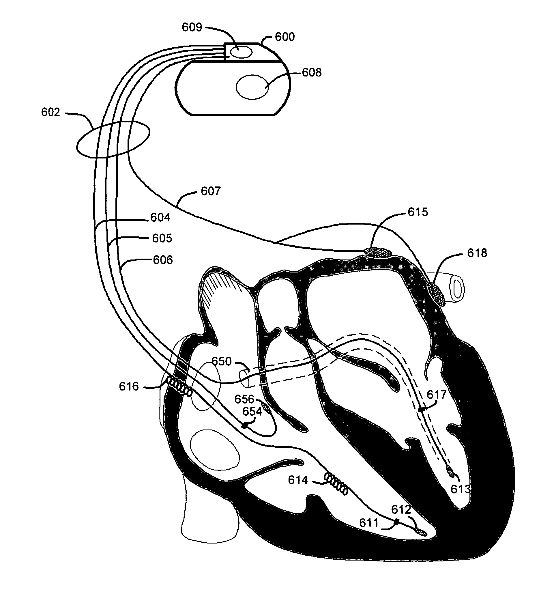
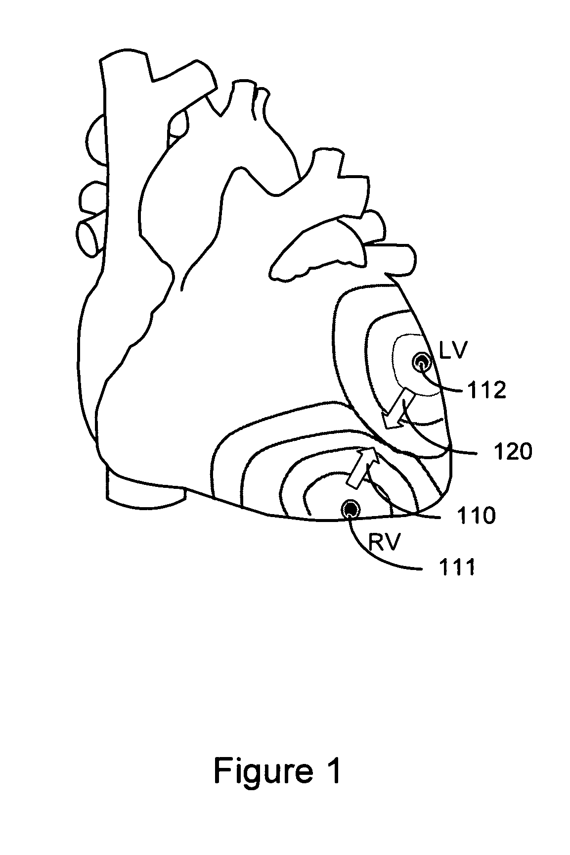
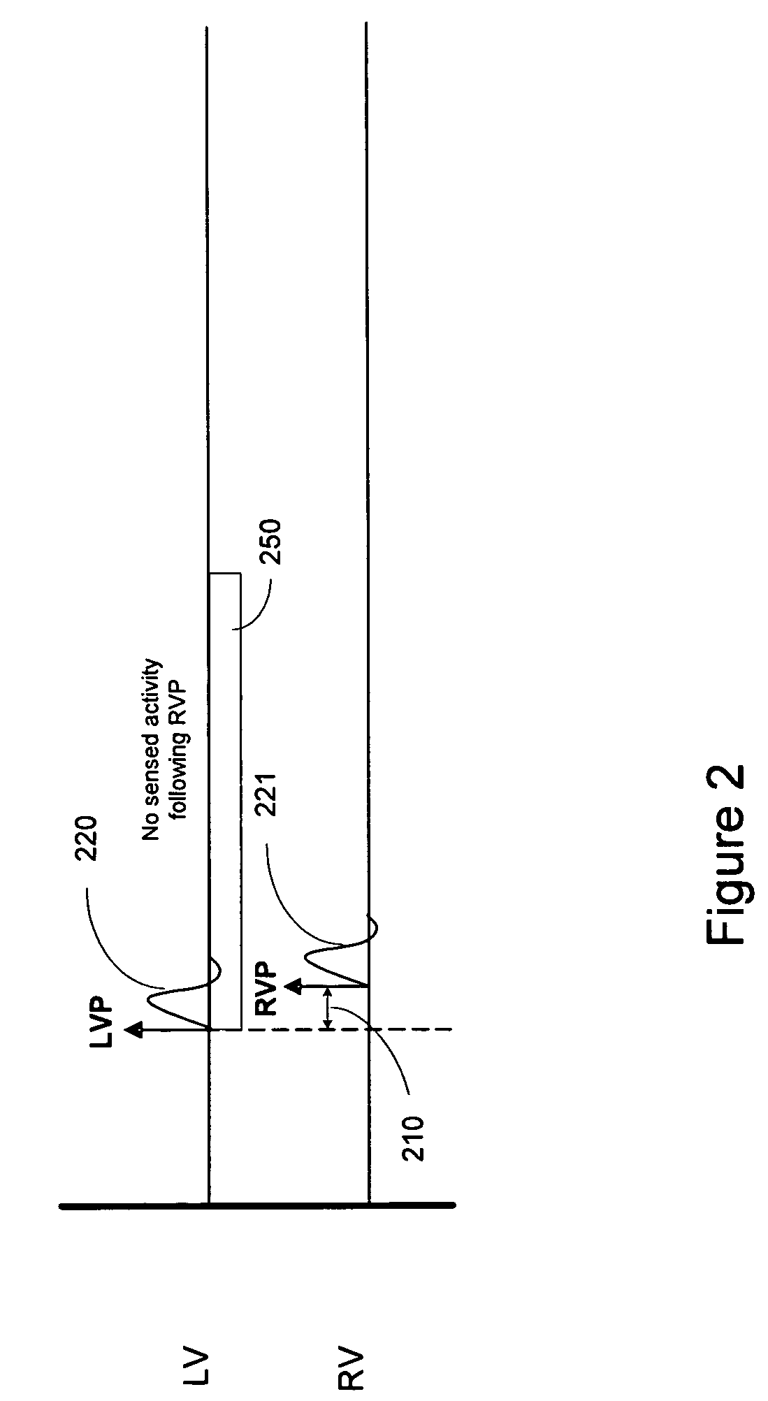
[0031]Capture detection methodologies in accordance with embodiments of the invention are based on cancellation of depolarization wavefronts caused by pacing pulses delivered to two or more pacing sites. In some implementations, the pacing sites may involve sites within a single cardiac chamber. In some implementations, the pacing sites may be located in contralateral cardiac chambers, e.g., right and left ventricles or right and left atria. In one embodiment, after delivering pacing pulses separated by an interventricular delay to right and left ventricles, the system sen...


PUM


Abstract

A methods and devices for capture detection are based on sensing a propagated depolarization from a contralateral cardiac chamber. An intersite sensing interval is determined based on an intersite pacing delay and an intersite conduction delay associated with first and second pacing sites. Pacing pulses are delivered to the first pacing site and the second pacing site, the pacing pulses separated in time by the intersite pacing delay. An intersite sensing interval is timed. The process includes sensing, during the intersite sensing interval, at the first pacing site for a depolarization propagated to the first pacing site from the second pacing site. It a depolarization propagated from the second pacing site is not sensed, then capture of the first and second pacing sites is detected.

Description

FIELD OF THE INVENTION[0001]The present invention relates generally to implantable medical devices and, more particularly, to capture threshold tests for determining capture of one or more heart chambers.BACKGROUND OF THE INVENTION[0002]When functioning normally, the heart produces rhythmic contractions and is capable of pumping blood throughout the body. However, due to disease or injury, the heart rhythm may become irregular resulting in diminished pumping efficiency. Arrhythmia is a general term used to describe heart rhythm irregularities arising from a variety of physical conditions and disease processes. Cardiac rhythm management systems, such as implantable pacemakers and cardiac defibrillators, have been used as an effective treatment for patients with serious arrhythmias. These systems typically comprise circuitry to sense electrical signals from the heart and a pulse generator for delivering electrical stimulation pulses to the heart. Leads extending into the patient's hea...

Claims


Application Information

Patent Timeline
Patent Type & Authority Patents(United States)
IPC IPC(8): A61N1/00
CPCA61N1/371
Inventor SATHAYE, ALOK S.BROOKE, M. JASONMEYER, SCOTT A.
Owner CARDIAC PACEMAKERS INC
Learn More