Linear ablation assembly

a linear ablation and assembly technology, applied in the field of linear ablation assembly, can solve the problems of inability to easily place avitall devices within the patient's atrial chamber, traumatic surgical technique, and inability to achieve the effect of facilitating the entry of the distal extremity, reducing the effective length of the elongated opening in the distal section of the delivery member, and reducing the effect of the elongated opening

Inactive Publication Date: 2008-02-19
SICHUAN JINJIANG ELECTRONICS SCI & TECH CO LTD
View PDF33 Cites 88 Cited by
  • Summary
  • Abstract
  • Description
  • Claims
  • Application Information

AI Technical Summary

Benefits of technology

[0010]In one presently preferred embodiment, the supporting member of the delivery member is a metallic ribbon which has an elongated flat surface which faces the elongated opening in the distal section of the delivery member. It may be made from high strength materials such as stainless steel, pseudoelastic NiTi alloys in an austenite phase. The support element is preferably manually shaped into a curved or angled condition to facilitate entry of the distal extremity of the assembly within the patient's heart chamber, particularly the right atrium, and the proper positioning of the extended distal section of the EP device against the inner surface of the heart chamber. Additionally, an elongated deflection line may be provided in a wall of the delivery member, for deflecting the distal section of the delivery member into a curved or angled condition.
[0011]The inner radius of the extended distal section of the EP device is controlled by the length of the elongated opening in the delivery member and the distance the EP device is spaced from the support element. The effective length of the elongated opening can be controlled by the longitudinal location of the distal end of a sheath disposed about the exterior of the delivery member. As the distal end of the sheath extends distally, the effective length of the elongated opening in the distal section of the delivery member is shortened and the radius of curvature of the distal section of the EP device is correspondingly decreased.

Problems solved by technology

However, the surgical technique is quite traumatic and is unacceptable to a large fraction of those patient's experiencing atrial fibrillation or flutter.
However, the Avitall device cannot be readily placed within the patient's atrial chamber and provide the necessary contact between the electrodes on the device and the atrial tissue to generate linear lesions of a requisite length when RF electrical energy is emitted from the electrodes.

Method used


Image

  • Linear ablation assembly
  • Linear ablation assembly
  • Linear ablation assembly

Examples


Embodiment Construction

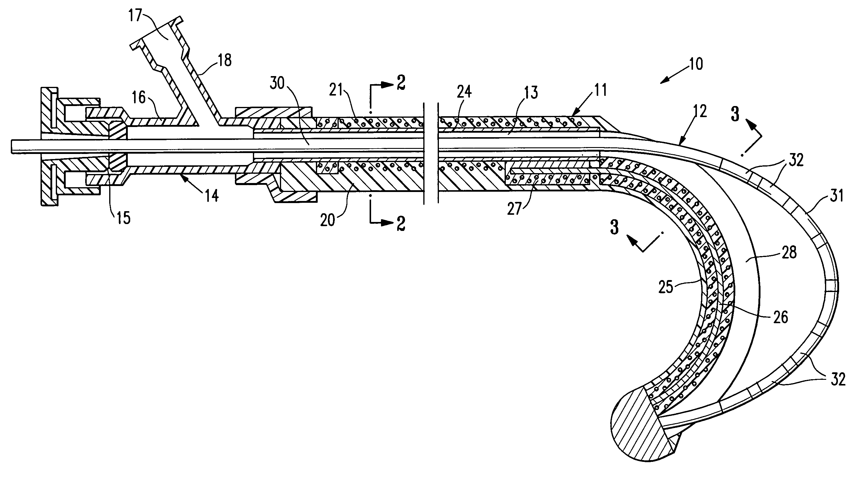
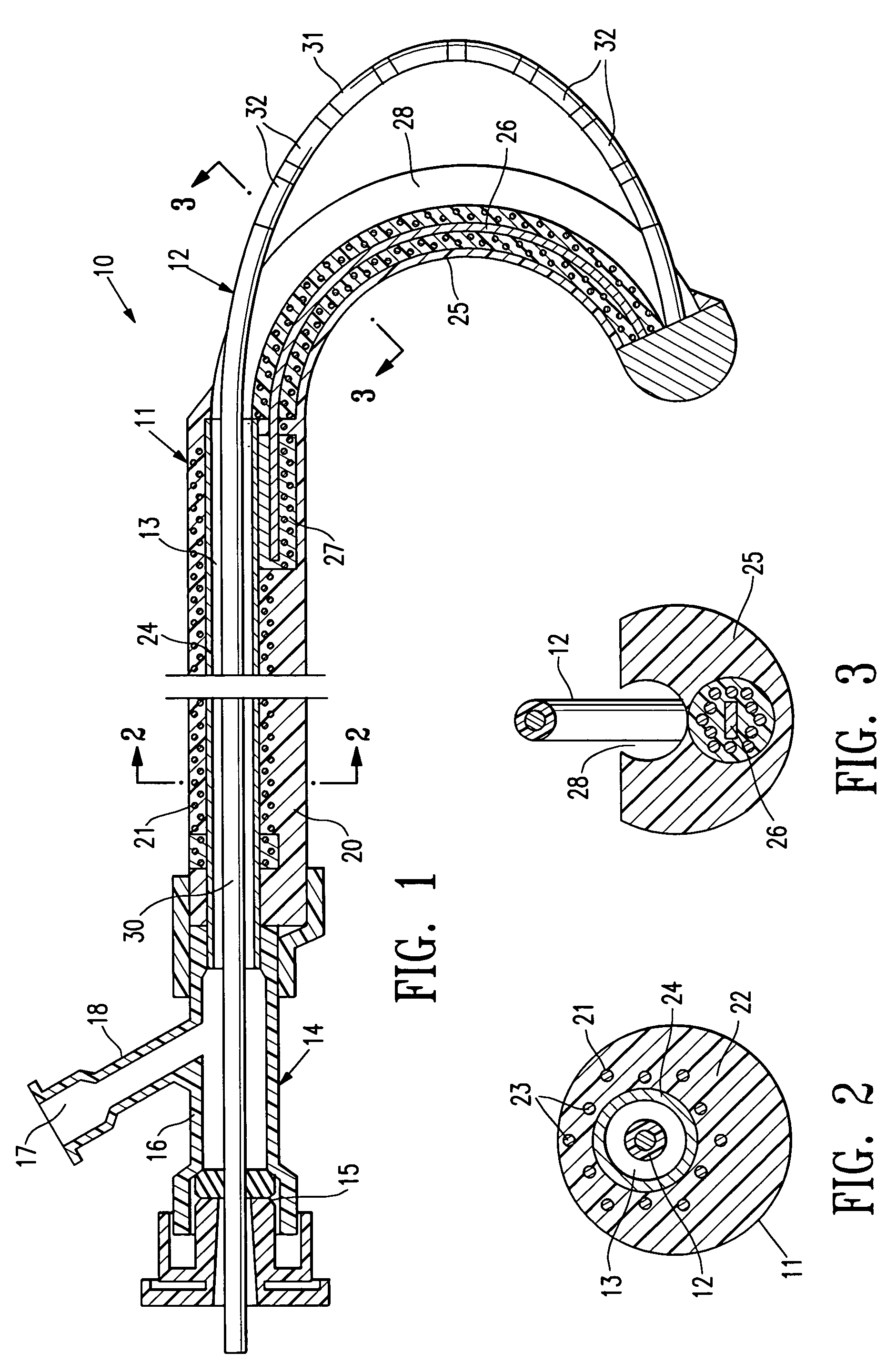
[0042]FIGS. 1-3 schematically depict a mapping / ablation assembly 10 embodying features of the invention which generally comprises a delivery member 11 and an elongated EP device 12 slidably disposed within the inner lumen 13 of the delivery member 11 with the distal end of the EP device secured within the delivery member 11. An adapter 14 is provided on the proximal end of the delivery member 11 with a hemostatic valve 15 on the proximal end of the central arm 16 of the adapter and with a flush port 17 in the proximal end of the side arm 18.

[0043]The delivery member 11 has a proximal shaft section 20 which is formed of a braided tubular structure 21 with a polymer impregnate 22 incorporated therein. The braided structure 21 may be formed of high strength filaments 23 (e.g. 6×6 strands) such as stainless steel wire with a typical diameter of about 0.003 inch (0.08 mm). The polymer impregnate is preferably a thermoplastic polyurethane such as PEBAX 6333. An inner lining 24 of high str...


PUM


Abstract

An intravascular device for the formation of linear lesions which has particular utility in the treatment of atrial fibrillation and flutter. The intravascular device has an outer delivery member with a distal section which has an elongated opening and a support element coextending with the opening. An EP device having a plurality of electrodes on its distal section is slidably disposed within the inner lumen of the delivery member but it is secured by its distal end within the distal extremity of the delivery member at least while in operation. In this manner an axial force in the proximal direction on the proximal extremity of the EP device, which extends out of the patient during the procedure, will cause the distal shaft section of the EP device to arch outwardly out of and away from the distal section of the delivery shaft along an inner side of the curved distal section and engage the surface of the patient's heart chamber. RF electrical energy delivered to the electrodes on the distal shaft section of the EP device will form a linear lesion which terminates the fibrillation or flutter.

Description

RELATED APPLICATIONS[0001]This application is a divisional of application Ser. No. 09 / 901,856, filed Jul. 9, 2001, now U.S. Pat. No. 6,814,732, which is a divisional of Ser. No. 09 / 182,967, filed Oct. 29, 1998, now U.S. Pat. No. 6,302,880, which is a continuation-in-part of Ser. No. 08 / 629,057, filed Apr. 8, 1996, now U.S. Pat. No. 5,863,291, which are incorporated herein in its entireties by reference and which priorities are claimed.BACKGROUND OF THE INVENTION[0002]This invention is a continuation-in-part of U.S. patent application Ser. No. 08 / 629,057, entitled LINEAR ABLATION ASSEMBLY, filed Apr. 8, 1996, the disclosure of which is incorporated by reference herein.[0003]This invention generally relates to the detection and elimination of cardiac arrhythmia and particularly atrial fibrillation.[0004]Atrial fibrillation is the disorganized depolarization of a patient's atrium with little or no effective atrial contraction. This condition may be chronic or intermittent, and it prese...

Claims


Application Information

Patent Timeline
Patent Type & Authority Patents(United States)
IPC IPC(8): A61B18/18A61N1/05A61B17/00A61B18/00A61B18/12A61B18/14A61M25/00A61M25/01A61N1/40
CPCA61B18/1492A61M25/0138A61M25/0144A61M25/0147A61M25/0152A61N1/403A61B2018/00029A61B2018/0016A61B2018/00577A61B2018/00797A61B2018/00821
Inventor SCHAER, ALAN K
Owner SICHUAN JINJIANG ELECTRONICS SCI & TECH CO LTD
Why Eureka
Try Eureka