Marine propulsion drive-by-wire control system with shared isolated bus

Active Publication Date: 2011-05-10
BRUNSWICK CORPORATION
View PDF9 Cites 29 Cited by
  • Summary
  • Abstract
  • Description
  • Claims
  • Application Information

AI Technical Summary

Benefits of technology

[0001]The invention relates to marine p

Problems solved by technology

With CAN bus node drop lengths, bus lengths and vessel routing limitations, the routing of the bus can be problematic.
As bus length is increased, propagation delay may be a concern.
With a single conductive bus, induced noise, e.g. electromagnetic interference, on the CAN bus propagates to the conductively coupled modules and controllers and can affect the bit sampling for the ECUs connected to the bus.
However, with implementations of more than two engines, three, four, five, six, etc. engines, such configuration makes it impossible t

Method used


Image

  • Marine propulsion drive-by-wire control system with shared isolated bus
  • Marine propulsion drive-by-wire control system with shared isolated bus
  • Marine propulsion drive-by-wire control system with shared isolated bus

Examples


Embodiment Construction

Prior Art

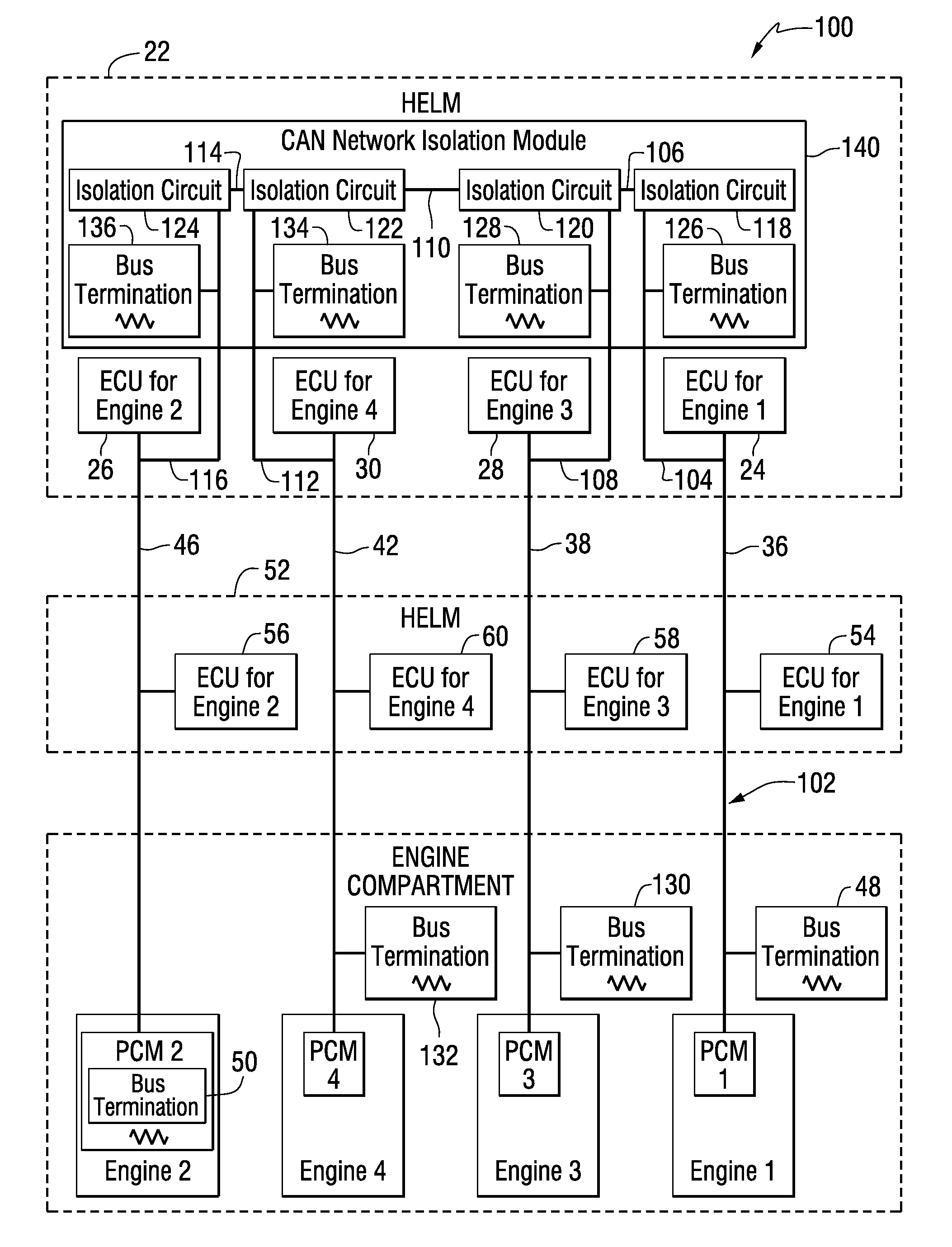
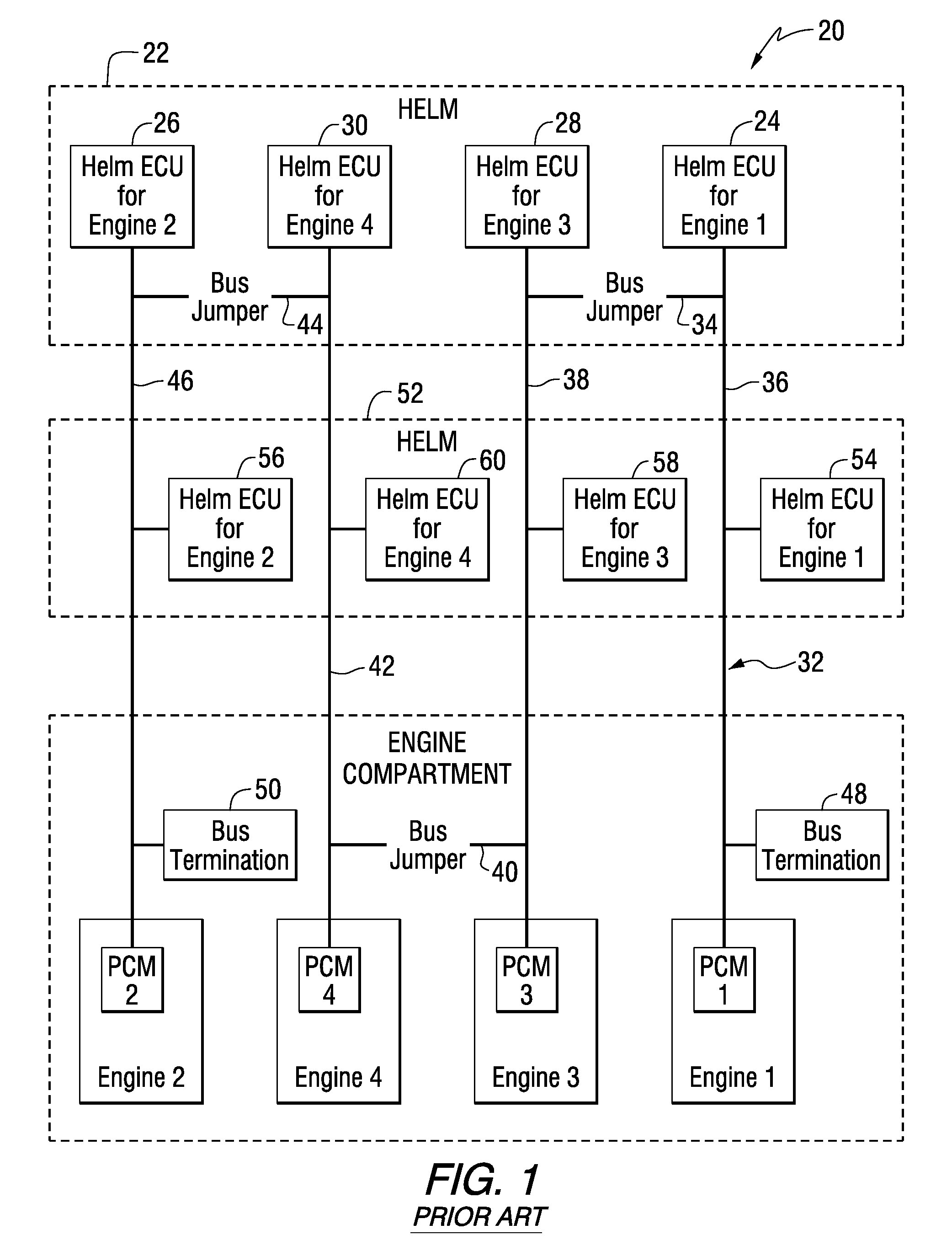
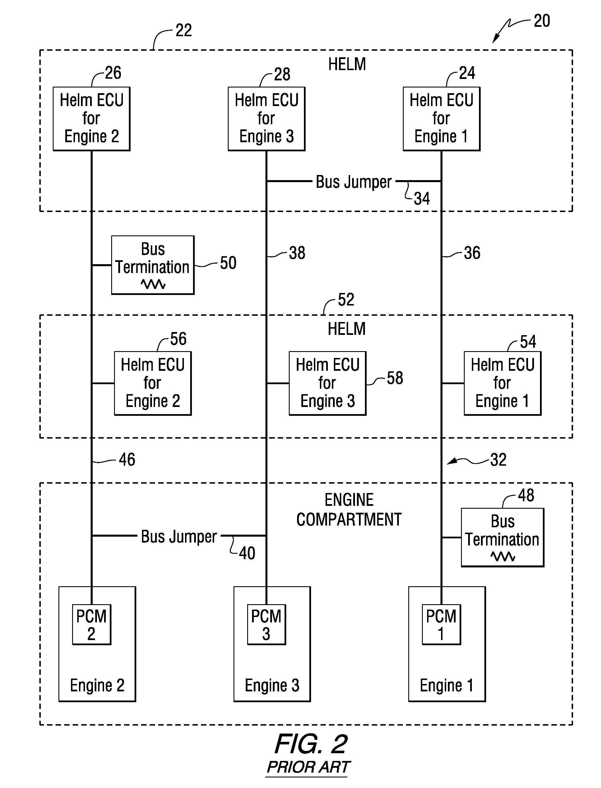
[0008]FIG. 1 shows a marine propulsion drive-by-wire control system 20 for multiple marine engines, such as engines 1, 2, 3, 4, each having a PCM, propulsion control module, such as PCM 1, PCM 2, PCM 3, PCM 4, as known in the prior art. Vessel helm 22 has multiple ECUs, electronic control units, for controlling the multiple marine engines, for example ECU 24 for controlling engine 1, ECU 26 for controlling engine 2, ECU 28 for controlling engine 3, ECU 30 for controlling engine 4. A CAN, controller area network, bus 32 connects the ECUs and PCMs, and includes bus jumpers connecting various portions of the bus so that the various components may communicate with each other via a shared bus, for example jumper 34 connecting buses 36 and 38, jumper 40 connecting buses 38 and 42, jumper 44 connecting buses 42 and 46. The CAN bus is terminated at its farthest ends, e.g. bus terminations 48 and 50. For redundancy, a second helm 52 also has multiple ECUs 54, 56, 58, 60 for controll...


PUM


Abstract

A marine propulsion drive-by-wire control system controls multiple marine engines, each one or more PCMs, propulsion control modules for controlling engine functions which may include steering or vessel vectoring. A helm has multiple ECUs, electronic control units, for controlling the multiple marine engines. A CAN, controller area network, bus connects the ECUs and PCMs with multiple PCM and ECU buses. The ECU buses are connected through respective isolation circuits isolating the respective ECU bus from spurious signals in another ECU bus.

Description

BACKGROUND AND SUMMARY[0001]The invention relates to marine propulsion drive-by-wire control systems.[0002]Marine propulsion drive-by-wire control systems are known in the prior art for controlling multiple marine engines each having a PCM, propulsion control module. A vessel helm has multiple ECUs, electronic control units, for controlling the multiple marine engines, and a CAN, controller area network, bus connecting the ECUs and PCMs. The systems are typically redundant, and include a second helm having multiple redundant ECUs for controlling the multiple marine engines.[0003]The present invention arose during continuing development efforts directed toward the above systems, and continuing improvements in reliability and integrity.BRIEF DESCRIPTION OF THE DRAWINGS[0004]FIG. 1 shows a marine propulsion drive-by-wire control system known in the prior art.[0005]FIG. 2 shows another marine propulsion drive-by-wire control system known in the prior art.[0006]FIG. 3 shows another marin...

Claims


Application Information

Patent Timeline
IPC IPC(8): B60L3/00
CPCB63H25/42B63H21/213
Inventor BRANT, JEFFERY A.
Owner BRUNSWICK CORPORATION
Why Eureka
Try Eureka