
Continuous fibers for use in well completion, intervention, and other subterranean applications

a technology of continuous fibers and subterranean wells, applied in the field of fiber-based evaluation, monitoring and/or controlling of hydraulic fracturing, can solve the problems of difficult hydrocarbon production, difficult interpretation, and inability to direct measurement, and achieve the effect of facilitating deployment and communication and sufficient redundancy

Inactive Publication Date: 2011-05-17
SCHLUMBERGER TECH CORP
View PDF13 Cites 2 Cited by
  • Summary
  • Abstract
  • Description
  • Claims
  • Application Information

AI Technical Summary

Benefits of technology

This approach provides direct and reliable measurement of fracture geometry, improving fluid management, reducing costs, and enhancing the accuracy of fracture characterization and control.

Problems solved by technology

As about 70% of the hydrocarbon present in a reservoir is not recovered by the initial recovery strategies, many challenges and opportunities exist for so-called brownfields concerning the tail production of the field.
In formations with low permeability, producing hydrocarbon is difficult.
To date, direct measurement is not possible, and the geometry is generally inferred from fracturing models, or interpretation of pressure measurements.
Still, this “hydraulic fracturing monitoring” or HFM technique is an indirect measurement for which interpretation is hard to verify.
In addition, it requires the mobilization of costly wireline borehole seismic assets that are not a very good fit for the economics of the hydraulic fracturing market on land; and a nearby offset well is normally required for monitoring.
However, such techniques can be prone to reliability issues due to poor deployment within fractures.
However, such techniques may in general be limited due to signal strength and power constraints on the discrete devices; and their cost is also an open question.

Method used


Image

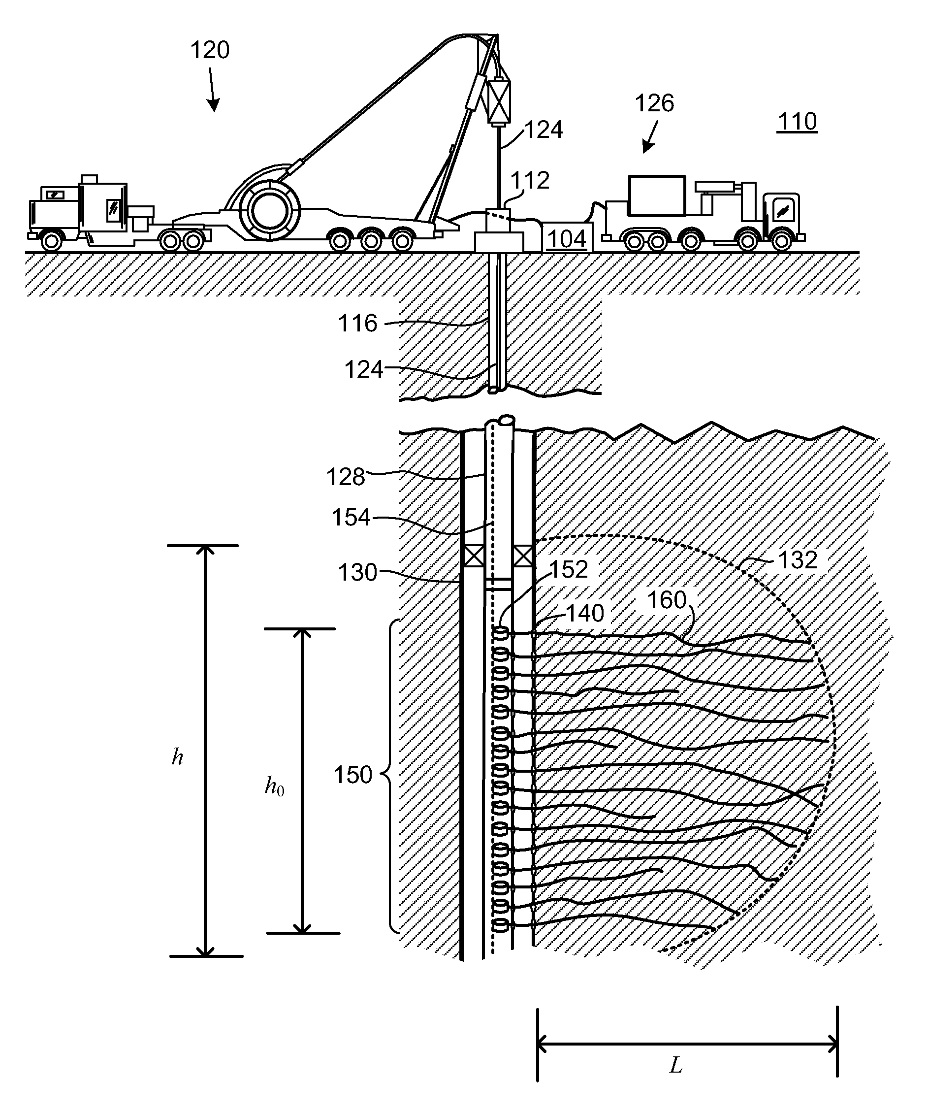
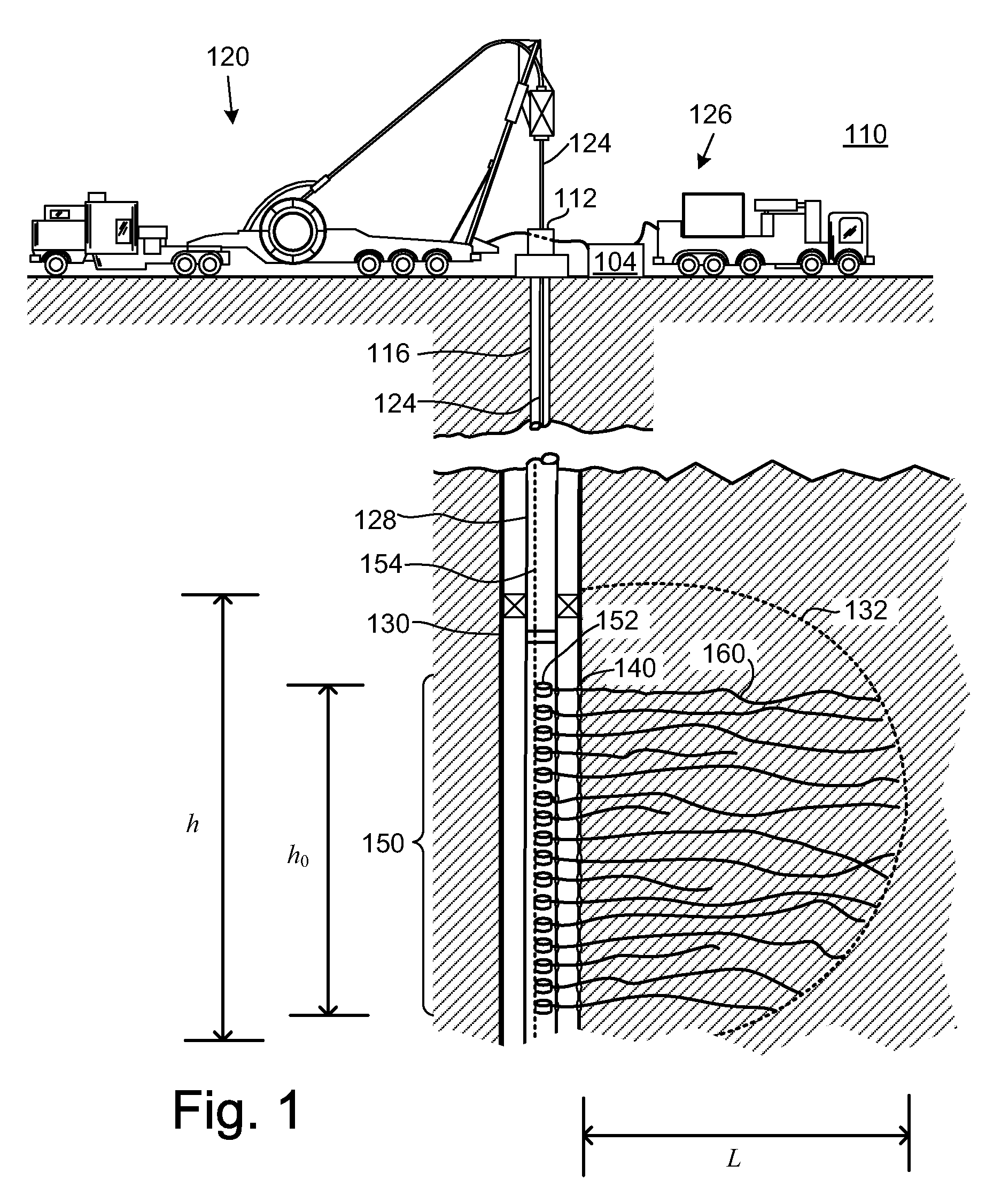
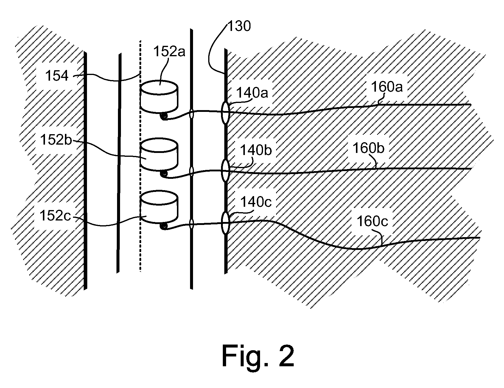
  • Continuous fibers for use in well completion, intervention, and other subterranean applications
  • Continuous fibers for use in well completion, intervention, and other subterranean applications
  • Continuous fibers for use in well completion, intervention, and other subterranean applications

Examples


Embodiment Construction

[0026]In the following detailed description of the preferred embodiments, reference is made to accompanying drawings, which form a part hereof, and within which are shown by way of illustration specific embodiments by which the invention may be practiced. It is to be understood that other embodiments may be utilized and structural changes may be made without departing from the scope of the invention.

[0027]The particulars shown herein are by way of example and for purposes of illustrative discussion of the embodiments of the present invention only and are presented in the cause of providing what is believed to be the most useful and readily understood description of the principles and conceptual aspects of the present invention. In this regard, no attempt is made to show structural details of the present invention in more detail than is necessary for the fundamental understanding of the present invention, the description taken with the drawings making apparent to those skilled in the...


PUM


Abstract

Methods and related systems for use with a continuous fiber based system for use with well bore completions. Wherein a plurality of continuous fibers are deployable into a portion of a well bore completion, such that a fiber management module is adapted and positioned within the borehole to facilitate deployment of and communication with the plurality of continuous fibers. Further, the number of deployable continuous fibers of the continuous fiber based system can provide for sufficient redundancy to make at least a target measurement relating to the completion.

Description

CROSS REFERENCE TO RELATED APPLICATIONS[0001]This patent application is related to the following commonly owned U.S. Patent Applications:[0002]1) U.S. patent application Ser. No. 12 / 121,302, filed on the same date as the present application entitled “CONTINUOUS FIBERS FOR USE IN HYDRAULIC FRACTURING APPLICATIONS”, which is incorporated by reference in its entirety for all purposes.[0003]2) U.S. patent application Ser. No. 12 / 121,311, filed on the same date as the present application entitled “SENSING AND MONITORING OF ELONGATED STRUCTURES”, which is incorporated by reference in its entirety for all purposes.[0004]3) U.S. patent application Ser. No. 12 / 121,325, filed on the same date as the present application entitled “SENSING AND ACTUATING IN MARINE DEPLOYED CABLE AND STREAMER APPLICATIONS”, which is incorporated by reference in its entirety for all purposes.BACKGROUND OF THE INVENTION[0005]1. Field of the Invention[0006]This patent specification relates to hydraulic fracture monit...

Claims


Application Information

Patent Timeline
Patent Type & Authority Patents(United States)
IPC IPC(8): E21B49/00E21B43/04
CPCE21B19/22E21B23/08E21B47/123E21B43/04E21B43/26E21B23/14E21B47/135
Inventor POITZSCH, MARTIN E.SEN, PABITRA N.WIEMER, KARENPICARD, GUILLEMETTEVEMBUSUBRAMANIAN, MUTHUSAMY
Owner SCHLUMBERGER TECH CORP
Learn More