Image forming method and image forming apparatus

a technology of inkjet image and forming method, which is applied in the field of inkjet image forming method and inkjet image forming apparatus, can solve the problems that prior art methods cannot achieve a balance between transfer stability and high throughput, and achieve the effects of reducing drying power, long drying time, and small value of y

Inactive Publication Date: 2011-05-17
CANON KK
View PDF6 Cites 32 Cited by
  • Summary
  • Abstract
  • Description
  • Claims
  • Application Information

AI Technical Summary

Benefits of technology

[0019]It should be noted that the “drying powers” means an amount of a component removed per unit of time, which is one of components contained in the ink and is most vaporizable, and is expressed Y (g / sec). The smaller the value of Y (g / sec), the lower the drying power is.
[0020]According to the above-described configuration, in the last drying step that most affects the transfer stability, the drying operation with low drying power (weak drying power) and long drying time is performed on giving a priority to the transfer stability. On the other hand, in the drying steps other than the last step that less affect the transfer stability, the drying operation with high drying power (strong drying power) and short drying time is performed on giving a priority to the high throughput. As a result, the balance between the transfer stability and the high throughput can be achieved.

Problems solved by technology

As described above, the prior art methods can not achieve a balance between the transfer stability and the high throughput.

Method used


Image

  • Image forming method and image forming apparatus
  • Image forming method and image forming apparatus
  • Image forming method and image forming apparatus

Examples


first embodiment

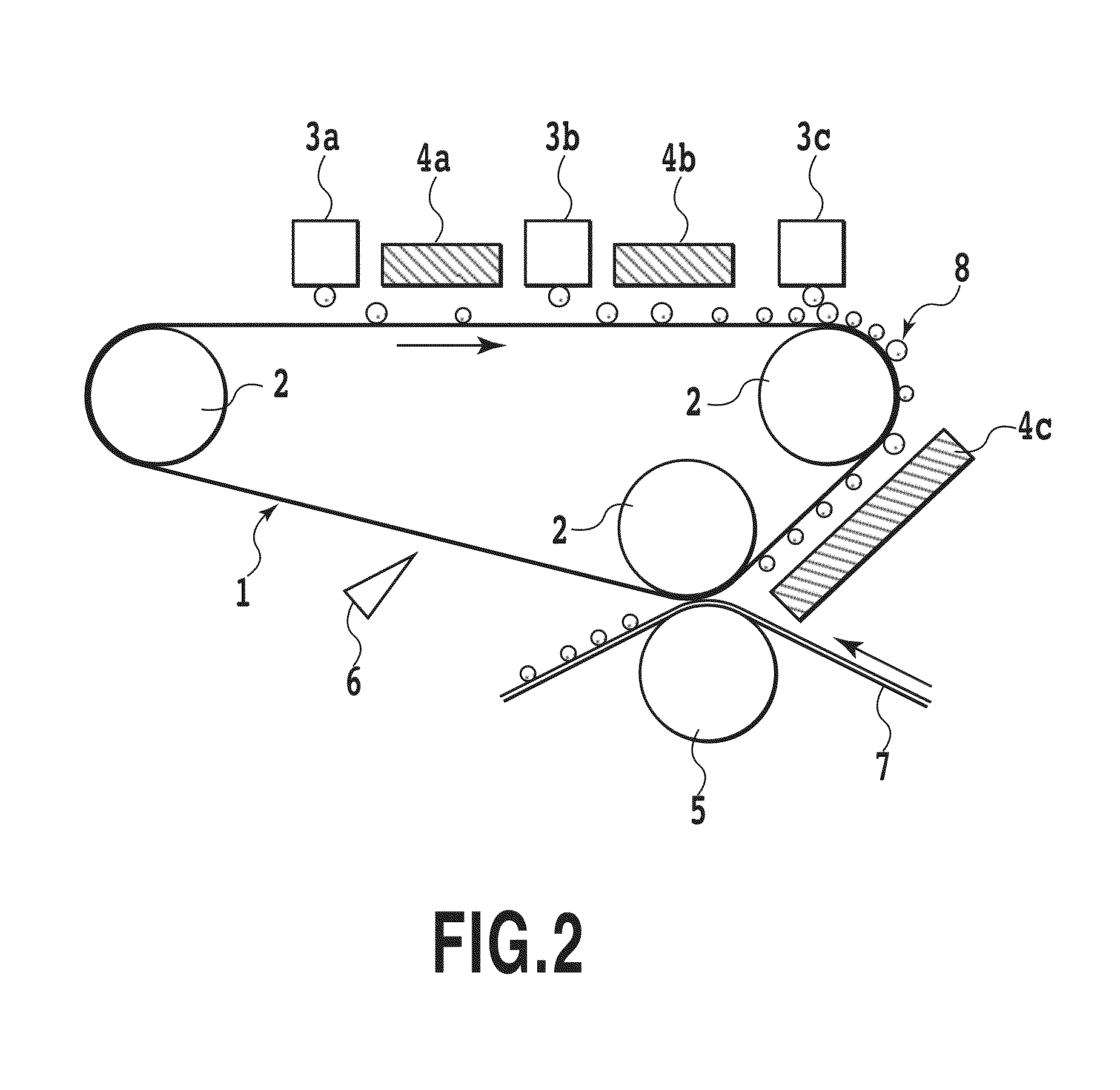
[0033]FIG. 2 is a schematic view illustrating an intermediate transfer body and configuration of its periphery of an image printing apparatus according to the present embodiment. The intermediate transfer body 1 is made up of an endless belt that is stretched around transfer body rotation rollers 2 and rotates in the direction of an arrow. Each of image forming portions 3a, 3b and 3c has an ink ejection head for ejecting ink by using an inkjet method and a reaction ejection head for ejecting a reaction liquid, which reacts on ink, by using the inkjet method. These ink and reaction liquid ejection heads respectively include ejection openings arranged across a width of the intermediate transfer body 1 that moves around and thus are called a full-line head. The image forming portions 3a, 3b and 3c respectively eject the ink and reaction liquid onto the intermediate transfer body and form an image on a surface layer of the intermediate transfer body 1. Drying portions 4a, 4b, and 4c dry...

second embodiment

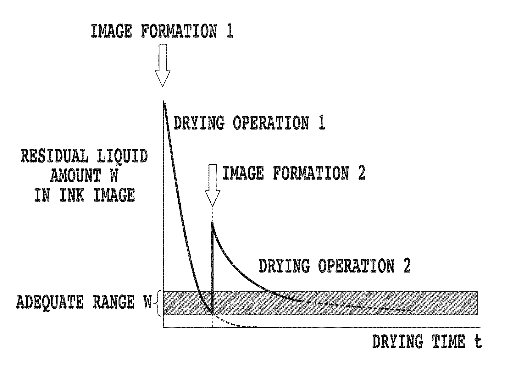
[0080]FIG. 4 is a view especially showing an image forming portion and a drying portion of a printing apparatus according to a second embodiment of the present invention. The printing apparatus of the present embodiment has basically same configuration as the first embodiment shown in FIG. 2, but has following differences. The printing apparatus according to the present embodiment has two sections each of which is consist of an image forming portion and a drying portion. The first section includes the image forming portion 3a and the drying portion 4a and the second section includes the image forming portion 3c and the drying portion 4c. That is, while the above described first embodiment performs three steps of image formation and drying, the present embodiment performs two steps of image formation and drying. Among the two steps of drying, as described later with reference to FIGS. 9 and 10, the first drying by the drying portion 4a is performed with high drying power and the seco...

third embodiment

[0112]FIG. 6 is a view a printing apparatus according to a third embodiment of the present invention. The present embodiment employs an intermediate transfer body 1 provided on a drum, in a palace of a belt-like intermediate transfer body shown in the above described embodiments. The intermediate transfer body 1 is formed on a surface of a drum 20. Specifically, the intermediate transfer body is made up by adhering a silicon rubber as the intermediate transfer body to the drum 20 in a predetermined thickness.

[0113]As shown in FIG. 6, around the intermediate transfer body 1 formed on the surface of the drum, an image forming portion 3 and a drying portion 4 are provided along a rotating direction of the drum. The drying portion 4 has two parts along the rotating direction into which a range for generating an air for drying is divided, and thus is controlled to selectively generate the air from one part at an upstream side in the rotating direction or from the two parts. Further, the ...


PUM


Abstract

Provided are an image forming method and image forming apparatus capable of always stably transferring an ink image on an intermediate transfer body to a printing medium and stably obtaining an image with high quality. Formation and drying operation of the image using an inkjet method are repeated a plurality of times to obtain the image on the intermediate transfer body and the thus obtained image is transferred from the intermediate transfer body to a printing medium to form the image. At this time, a capability of the drying operation finally performed among a plurality of times of the drying operations is more lowered than those of all the drying operations except the drying operation finally performed.

Description

BACKGROUND OF THE INVENTION[0001]1. Field of the Invention[0002]The present invention relates to an inkjet image forming method and an inkjet image forming apparatus. Specifically, the present invention relates to an image forming method and an image forming apparatus that form an ink image on an intermediate transfer body by using a inkjet method and transfer the ink image to a printing medium for performing printing.[0003]2. Description of the Related Art[0004]Recently, there is growing a request for taking advantage of an inkjet printing method and outputting an image with high quality using an inkjet printing method regardless of types of a printing medium. For example, there is a request for performing printing onto a printing medium that does not absorb any aqueous ink composition, such as plastics or metal (hereinafter, also referred to as “non-ink-absorbency”). Also, there is a request for performing printing onto a printing medium in which the amount of absorbing aqueous in...

Claims


Application Information

Patent Timeline
Patent Type & Authority Patents(United States)
IPC IPC(8): B41J2/01
CPCB41J2/0057
Inventor OHARA, MIDORITANIUCHI, HIROSHI
Owner CANON KK
Why Eureka
Try Eureka