Connector having contacts with a linkage portion having a width smaller than that of the contact portion

a technology of connecting parts and contact parts, applied in the direction of coupling contact members, coupling device connections, coupling protective earth/shielding arrangements, etc., can solve the problems of reducing the contact area between the first and second contact parts, the connector and the associated first, and the fear of contact failur

Inactive Publication Date: 2011-05-17
JAPAN AVIATION ELECTRONICS IND LTD
View PDF8 Cites 2 Cited by
  • Summary
  • Abstract
  • Description
  • Claims
  • Application Information

AI Technical Summary

Benefits of technology

[0013]The present invention has been made in view of these circumstances, and an object thereof is to provide a connector which is capable of maintaining contact reliability even if the arrangement pitch of contacts is reduced.
[0015]With the arrangement of the connector according to the present invention, the first contact portions are disposed on one surface of the contact arranging portion, and the second contact portions and the linkage portions are disposed on the other surface of the contact arranging portion. Further, each linkage portion is made smaller in width in the contact arrangement direction than the first and second contact portions. Therefore, it is possible to reduce the arrangement pitch of the first and second contact portions without reducing the width of the first and second contact portions in the contact arrangement direction.
[0020]According to this invention, even if the arrangement pitch of the contacts is reduced, it is possible to maintain contact reliability.

Problems solved by technology

However, if the width of each of the first and second contact portions in the contact arrangement direction is reduced in order to reduce the arrangement pitch of the signal contacts, misalignment of the first and second contact portions of the plug connector and the first and second contact portions of the receptacle connector, which can be caused e.g. by loose or inaccurate fitting, reduces areas of contact between the first and second contact portions of the receptacle connector and the associated first and second contact portions of the plug connector.
In such a case, there is a fear of occurrence of contact failure.

Method used


Image

  • Connector having contacts with a linkage portion having a width smaller than that of the contact portion
  • Connector having contacts with a linkage portion having a width smaller than that of the contact portion
  • Connector having contacts with a linkage portion having a width smaller than that of the contact portion

Examples


Embodiment Construction

[0043]The present invention will now be described in detail with reference to the drawings showing preferred embodiments thereof. A description will be given of a plug connector of an embodiment of the present invention with reference to FIGS. 1 to 20.

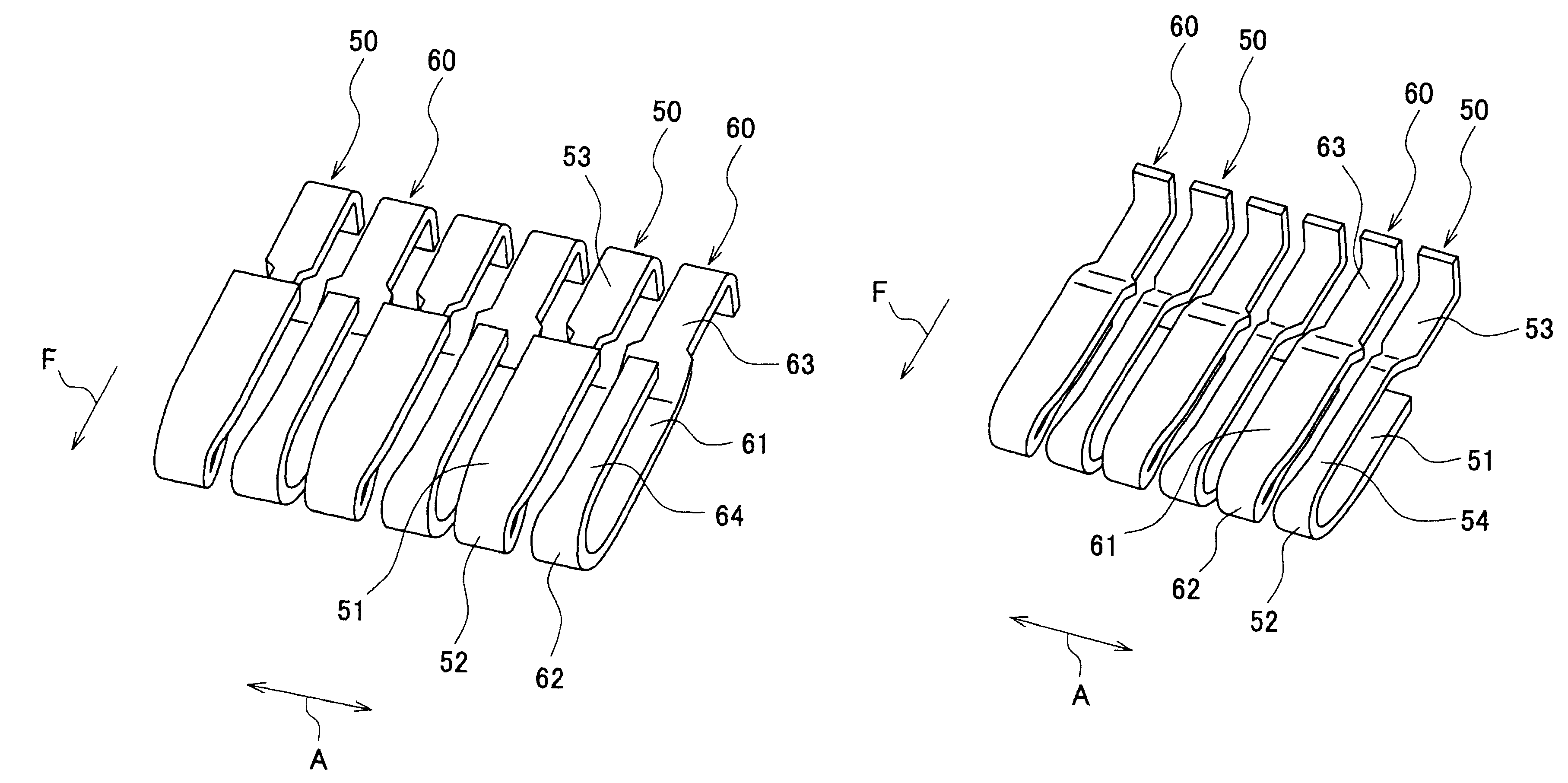
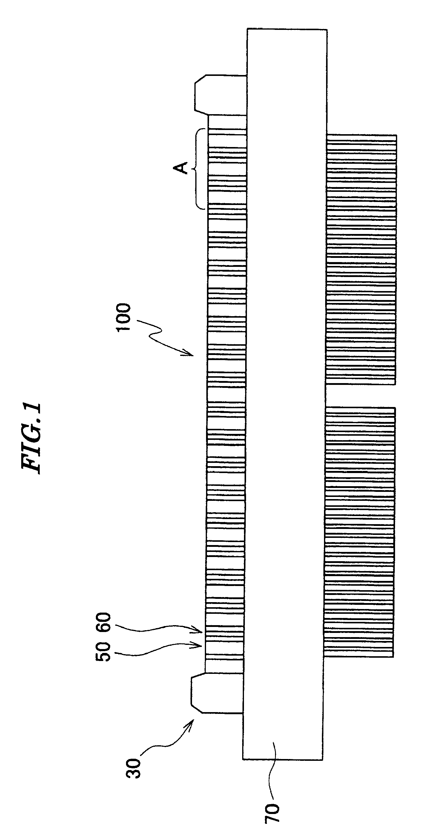
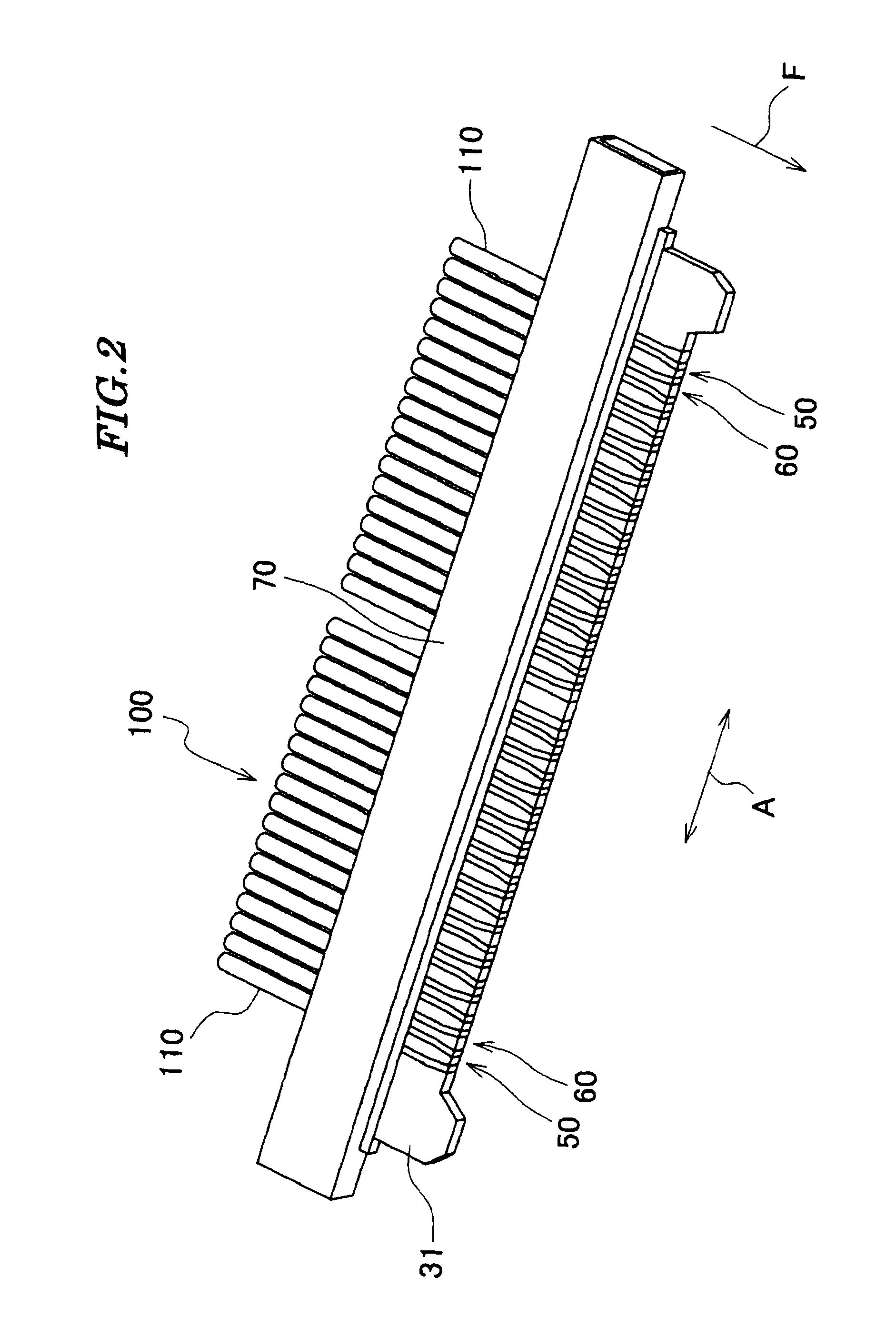
[0044]As shown in FIGS. 1 to 4, a plug connector (connector) 100 is comprised of a housing 30, a plurality of first contacts 50, a plurality of second contacts 60, a cover shell 70, and a base shell 80.

[0045]As shown in FIGS. 1 and 4, the first contacts 50 and the second contacts 60 are arranged in the housing 30 in an alternating manner in a contact arrangement direction A.

[0046]The housing 30 is integrally molded of an insulating material. As shown in FIGS. 7 and 8, a contact arranging portion 31 is disposed on a front portion of the housing 30, and a cable holding portion 32 is disposed on a rear portion of the housing 30. In the present embodiment, the front portion of the housing 30 corresponds to a lower portion as viewed in FIGS...


PUM


Abstract

A connector capable of maintaining contact reliability even with reduced arrangement pitch of contacts. First and second contacts are alternately arranged on a housing along contact arrangement direction orthogonal to direction of fitting the housing to a receptacle connector. A first contact portion, first bending portion, and first connecting portion connected to a coaxial cable, of each first contact are disposed on an upper surface, front portion and rear portion of the arranging portion, respectively. A linkage portion connecting the first bending and connecting portions, and a second contact portion continuous with a second connecting portion of each second contact are disposed on a lower surface of the arranging portion. A second bending portion disposed on the front portion is continuous with the second contact portion. The linkage portion is smaller in width in the arrangement direction than the first and second contact portions.

Description

BACKGROUND OF THE INVENTION[0001]1. Field of the Invention[0002]This invention relates to a connector.[0003]2. Description of the Related Art[0004]Conventionally, there has been proposed a plug connector comprised of a housing and a plurality of signal contacts (see Japanese Laid-Open Patent Publication (Kokai) No. 2008-293916 (paragraphs 0027 to 0029, 0032, and 0033; FIG. 1)).[0005]The housing has a plate-shaped projecting portion in which are arranged first and second contact portions, referred to hereinafter, of the signal contacts.[0006]The signal contacts are held on the housing at a predetermined pitch along a contact arrangement direction which is orthogonal to a direction of fitting the housing to a mating connector. Each signal contact has a first contact portion and a second contact portion. The first contact portion is disposed on an upper surface of the projecting portion of the housing. The second contact portion, which is continuous with the first contact portion, is b...

Claims


Application Information

Patent Timeline
Patent Type & Authority Patents(United States)
IPC IPC(8): H01R13/648
CPCH01R12/592H01R13/26H01R12/722
Inventor NANAO, SHINGOYAHIRO, YASUFUMIKIKUCHI, MASAYUKIKAI, KEIZOKAMATA, KAZUSHI
Owner JAPAN AVIATION ELECTRONICS IND LTD
Why Eureka
Try Eureka