Treating valve failure

a valve failure and valve annulus technology, applied in the field of valve failure treatment, can solve the problems of valve failure, valve failure, and deficiency or failure of valves in the circulatory system, and achieve the effect of facilitating the engagement of one or more engaging zones

Inactive Publication Date: 2011-05-17
KAYE DAVID +2
View PDF62 Cites 216 Cited by
  • Summary
  • Abstract
  • Description
  • Claims
  • Application Information

AI Technical Summary

Benefits of technology

[0018]wherein the device is compressible for percutaneous delivery to the valve, and wherein the engaged device, when in the predetermined configuration, constricts the valve annulus facilitating substantial closure of leaflets of the valve.
[0044]Preferably the apparatus includes retaining means to retain the position of the repair device relative to the valve while the device is being expanded and / or engaged with the valve annulus. The retaining means may be a hook or anchor or a temporary guide wire with a helical screw at the tip or other suitable means capable of stabilising the device and deployment apparatus during deployment and implantation of the repair device and removed afterwards. This may occur by temporarily embedding the retaining means in an endocardial wall or the apex of the ventricle or other nearby tissue, without causing serious damage to that tissue.

Problems solved by technology

In some cases, valves in the circulatory system such as the tricuspid and mitral heart valves are deficient or fail.
However, the most common cause of valve failure is dilation of the valve annulus.
The consequences of heart valve failure can vary depending on the seriousness of the failure, but in most cases the heart's efficiency and the efficiency of the circulatory system is seriously affected and complications often result.
Failure or leakage of the heart valves frequently results in mitral / tricuspid valve regurgitation.
In the case of the mitral valve, regurgitation results in back pressure in the lungs, whereas tricuspid valve regurgitation can result in high back pressures in the venous circulation.
Clearly, this is undesirable for the health of the heart, as well as for the lungs and other organs of the body.
Mitral and tricuspid valve failure can lead to ineffective and / or inefficient cardiac pumping, ventricular and atrial enlargement, pulmonary and / or circulatory hypertension, heart failure and in some cases, death.
Concomitant with the seriousness of such procedures are an increase in morbidity and mortality risk, and a slow and painful period of rehabilitation which follows.
Because of this, the options available for patients experiencing tricuspid valve regurgitation are limited.
The location of the tricuspid valve in the right heart complicates treatment because it is less easily accessible than the mitral valve, and it has a more complex triple-leaved structure.
However, unlike the CS / GCV, this vessel is small, variable in size and absent in approximately 50% of cases.
Therefore, reasonable vascular access to the tricuspid annulus is limited to a right atrial approach.

Method used


Image

  • Treating valve failure
  • Treating valve failure
  • Treating valve failure

Examples


Embodiment Construction

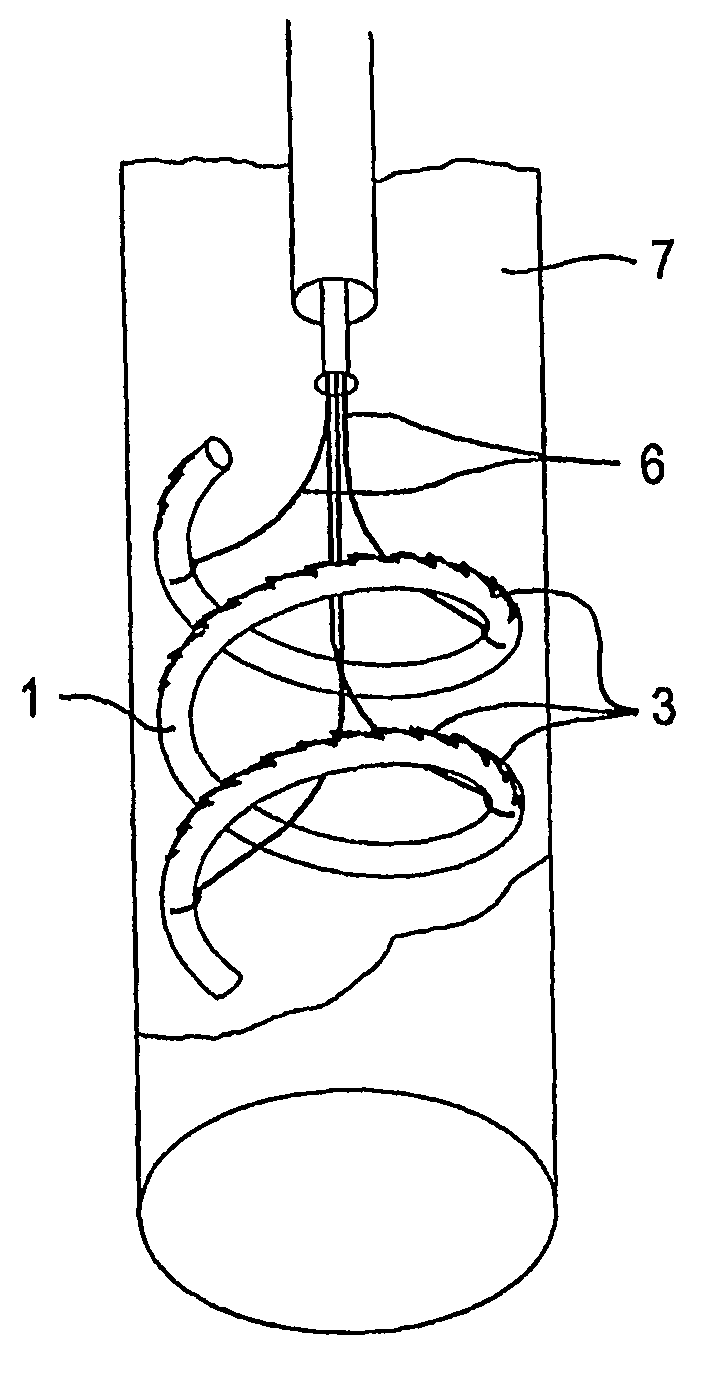
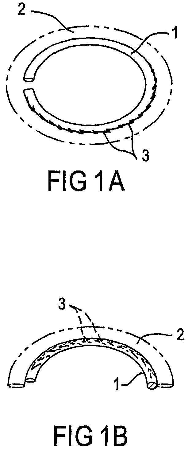
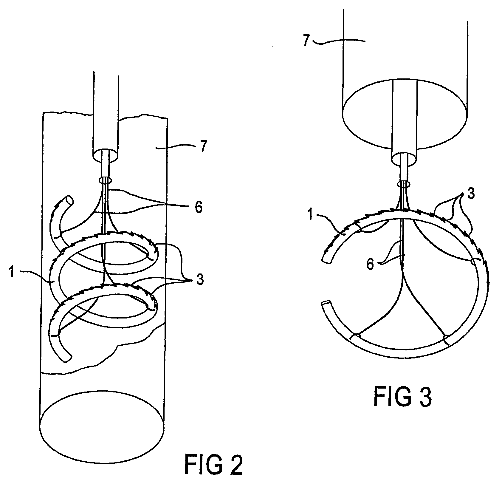
[0052]Referring firstly to FIG. 1A there is shown a device (generally shown as 1) for treating failure of a valve such as the tricuspid or mitral valve of the heart. The device includes one or more engaging zones 3 for engaging the device with the valve annulus 2, the fibrous ring of tissue from which the leaflets of the valve extend. The device also includes pre-disposition means which, in a preferred embodiment of the invention, is inherent in the material from which the device is manufactured. In such an embodiment, the material is preferably nitinol, a shape memory alloy which can be “programmed” to have a pre-determined configuration when situated, unconfined, in an environment having a particular temperature. Implantation in the human body (or other animal body) is one such environment in which devices formed from nitinol or equivalent material exhibit these “shape memory” characteristics, realising their pre-determined configuration.

[0053]In one preferred embodiment, the devi...


PUM


Abstract

A device (1) for treating valve failure in a patient is provided. The device has one or more engaging zones (3) for engaging the device with the annulus of the valve being treated. The device also has pre-disposition means for changing the geometry of the device to a predetermined configuration which is suitable for constricting the valve annulus. The device is compressible for percutaneous delivery to the valve. When in the predetermined configuration, the engaged device constricts the valve annulus facilitating substantial closure of leaflets of the valve.

Description

[0001]This application is a national stage application under 35 U.S.C. §371 from PCT Application No. PCT / AU2005 / 000333, filed Mar. 9, 2005, which claims the priority benefit of Australian Application No. 2004901357, filed Mar. 15, 2004, and U.S. Provisional Application No. 60 / 559,784, filed Apr. 6, 2004.FIELD OF THE INVENTION[0002]The present invention relates to a method and apparatus for treating valve failure. In particular, the invention relates to a device and method for treating failure of valves of the heart including the tricuspid valve.BACKGROUND TO THE INVENTION[0003]The body's circulation is facilitated by the heart, the cardiac pump which ensures that fresh blood is supplied throughout the body delivering nutrients to organs and transporting waste products to the body's filtration systems. The heart, illustrated in section in FIG. 5, is a complex organ operating two pumping systems. One pumping system includes the left ventricle (LV) and left atrium (LA) and services the...

Claims


Application Information

Patent Timeline
Patent Type & Authority Patents(United States)
IPC IPC(8): A61F2/24
CPCA61F2/2445
Inventor KAYE, DAVID MARTINPOWER, JOHN MELMOUTHALFERNESS, CLIFTON A.BILNEY, ADAM LUCAS
Owner KAYE DAVID
Why Eureka
Try Eureka