In-flight detection of wing flap free wheeling skew

a technology of in-flight detection and wing flap deflection, which is applied in the field of aircraft flight sensors, can solve the problems of low accuracy of flap sensors, more serious failure, and inability to detect the type of failure usually not obvious, and achieve the effect of accurate and reliable detection of small flap surface deflection during fligh

Active Publication Date: 2011-05-17
THE BOEING CO
View PDF13 Cites 19 Cited by
  • Summary
  • Abstract
  • Description
  • Claims
  • Application Information

AI Technical Summary

Benefits of technology

[0009]In accordance with the present disclosure, methods and apparatus are provided for detecting small wing flap deflections caused by aerodynamic loads acting on the flap during flight using existing flap sensors that can have measurement errors of the same magnitude as the small deflections being detected. The system accurately and reliably detects small flap surface deflections during flight that are indicative of flap freewheeling skew, i.e., disconnect failures, of the flap structure or drive system.
[0011]The detection system uses existing, low-accuracy flap sensors to accurately and reliably detect small flap surface deflections during flight that are indicative of flap freewheeling skew. This eliminates the weight and cost of additional sensors, their installation costs and the additional wiring and interfaces attendant thereto, and further, avoids any drive system reliability issues associated with adding additional sensors.

Problems solved by technology

Due to the stiffness of the flaps, this creates only small deflections when aerodynamic loads are applied to the flap during flight.
However, if this type of failure goes undetected, the flap can become completely disconnected from the aircraft, resulting in a more serious failure.
Additionally, this type of failure is usually not obvious when the aircraft is at rest or taxiing on the ground because the disconnected side of the flap will not droop conspicuously, due to the stiffness of the flap and the configuration of the flap-to-aircraft connection structure.
The problem becomes one of detecting small flap deflections with a light weight system that uses existing, low-accuracy flap sensors that have measurement errors of the same order of magnitude as the small deflections being measured to detect freewheeling skew.
These solutions function by preventing the flap from becoming disconnected from the aircraft, and hence, are relatively heavy and require costly periodic inspections to detect failures.
Hence, the multiple load path solution is acceptable only if no other solutions exist, because it adds substantial weight, cost and complexity to the aircraft.
Additionally, for certain other types of flap configurations, a flap skew failure is readily obvious, even when the aircraft is situated on the ground, because the disconnected side of the flap will droop conspicuously, and hence, can be readily detected on a typical pre-flight “walk-around” of an aircraft having this type of flap configuration.
However, visual detection during a walk-around is only applicable to certain aircraft having a different type of flap configuration than the ones contemplated herein.

Method used


Image

  • In-flight detection of wing flap free wheeling skew
  • In-flight detection of wing flap free wheeling skew
  • In-flight detection of wing flap free wheeling skew

Examples


Embodiment Construction

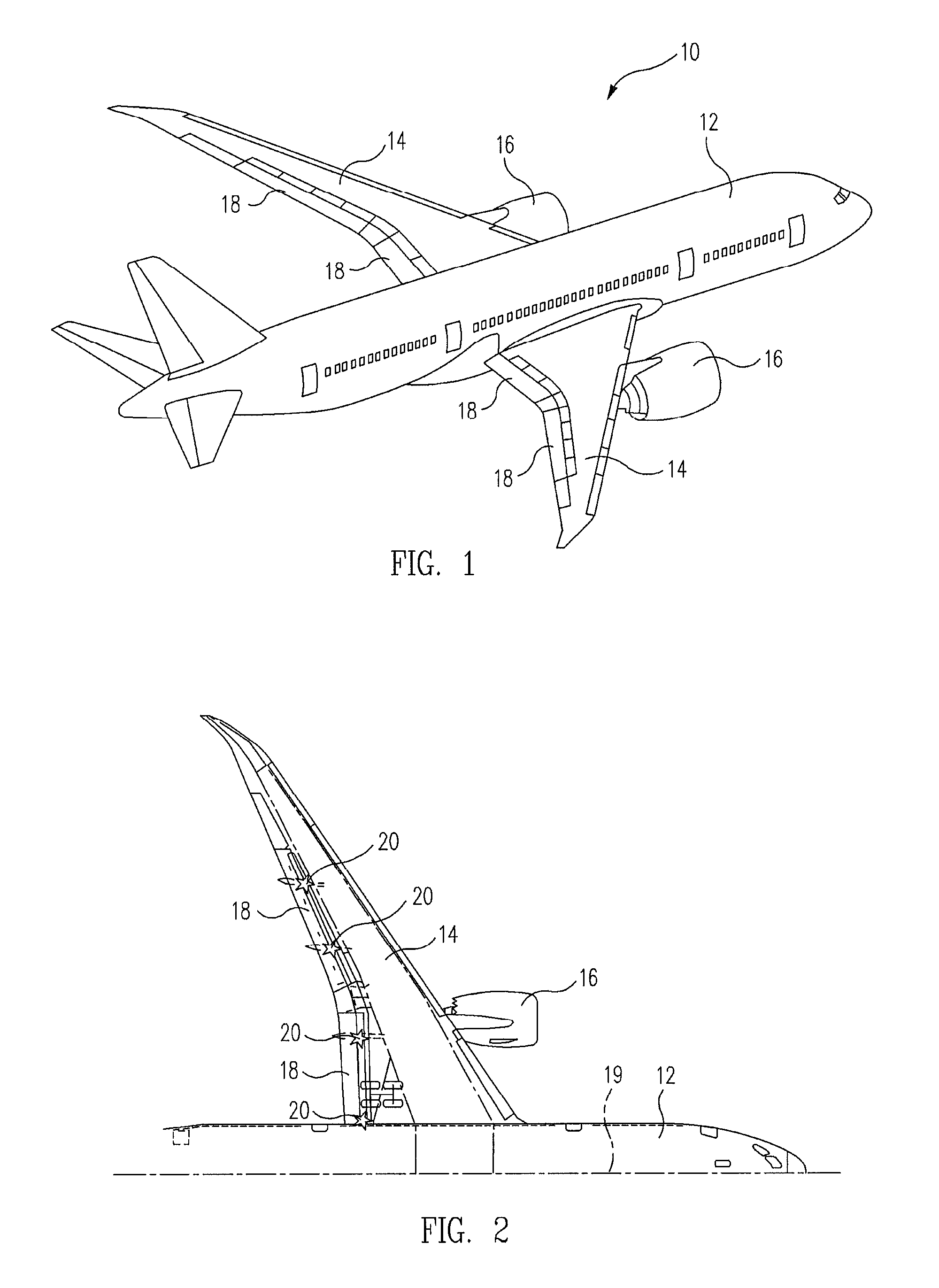
[0019]FIGS. 1 and 2 are perspective and partial top plan views of a modern jet aircraft 10 of a type to which the freewheeling skew detection system and methods of the present disclosure have advantageous application. With reference to FIGS. 1 and 2, the aircraft comprises an elongated fuselage 12 having a pair of sweptback wings 14 respectively disposed on opposite sides thereof that are adapted to generate lift as the aircraft moves through the air. Each wing includes a jet engine 16 supported on a pylon below the wing and a pair of flaps 18 supported at the trailing edge (TE) thereof by a pair of flap drive mechanisms 20 for extension, i.e., pivotal and translational movement relative to the TE of the wing. As illustrated in FIGS. 1 and 2, the flaps are disposed symmetrically with respect to the sagittal plane 19 of the aircraft and, in operation, are extended and retracted simultaneously with each other.

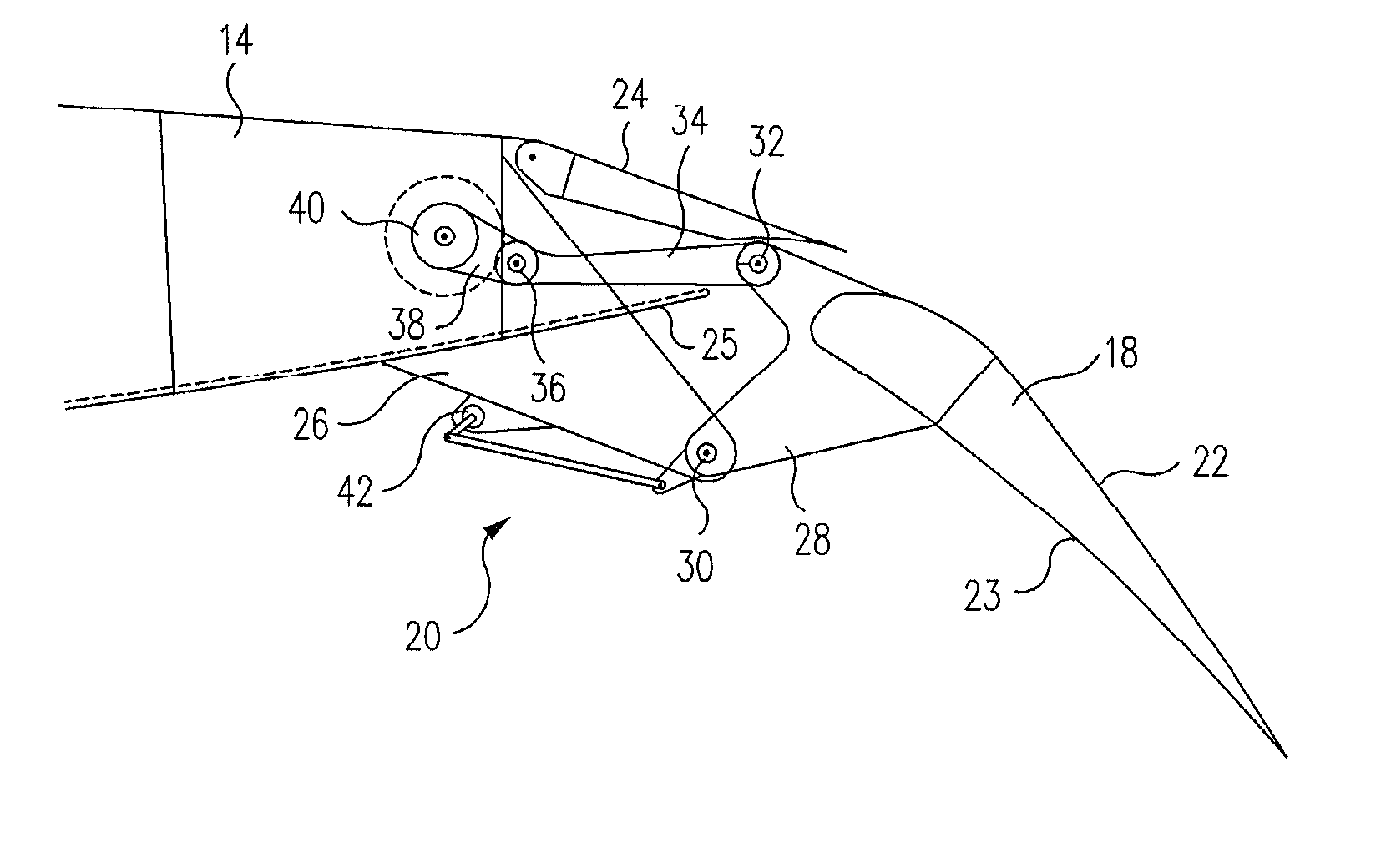
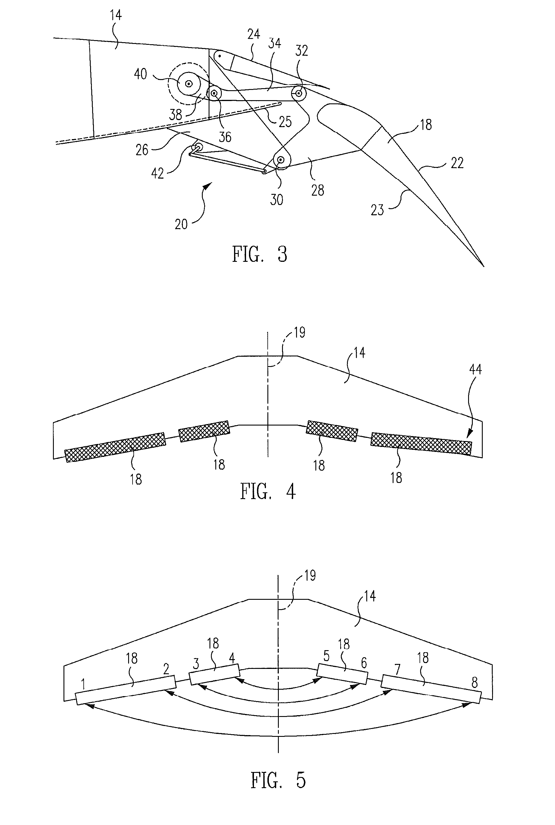
[0020]FIG. 3 is a partial cross-sectional view of one of the TE flaps 18 of ...


PUM


Abstract

A method for detecting freewheeling skew failures in the wing flaps of an aircraft includes measuring the outputs of flap skew sensors when the aircraft is in flight (IF) and the flaps are extended to a selected position, and when the aircraft is next on the ground (OG) and the flaps are extended to the selected position. The respective differences between the IF and OG outputs of symmetrical pairs of the flap skew sensors are computed, and then the respective difference between the computed IF output difference and the computed OG output difference of each symmetrical pair of the sensors is computed. The computed IF and OG difference of each symmetrical pair of the sensors is then compared with each of predetermined maximum and minimum threshold value to determine whether a freewheeling skew failure exists in any of the flaps of the aircraft.

Description

BACKGROUND[0001]1. Technical Field[0002]This disclosure relates to aircraft flight sensors in general, and in particular, to a system for the in-flight detection of small wing flap deflections that are indicative of failures of the flap structure or flap drive mechanism using existing flap sensors that have measurement errors on the same order of magnitude of the small deflections being detected.[0003]2. Related Art[0004]Flaps are airfoil surfaces moveably coupled to the trailing edge (TE) of the wings of a fixed-wing aircraft by means of powered hinging / lowering drive mechanisms typically located at the opposite ends of each flap. As the flaps are lowered and / or extended relative to the wing during landing, lift and drag are increased to permit slower approach speeds and greater maneuverability. Other types of flaps, referred to as “slats” or “Krueger flaps,” may also be used on the leading edge of the wings of some high-speed jet aircraft.[0005]Certain failures of the structural m...

Claims


Application Information

Patent Timeline
Patent Type & Authority Patents(United States)
IPC IPC(8): G06F11/30
CPCB64D45/0005B64D2045/001
Inventor MARX, ALAN D.EMCH, GARY A.GARDNER, MARK J.APFEL, RICHARD I.RENZELMANN, MICHAEL E.FEET, CHRISTOPHER D.FINN, MICHAEL R.GOOD, MARK S.SEEHUSEN, GREGORY J.
Owner THE BOEING CO
Why Eureka
Try Eureka