
Apparatus structure and scanning probe microscope including apparatus structure

a scanning probe and apparatus technology, applied in the direction of mechanical roughness/irregularity measurement, measurement devices, instruments, etc., can solve problems such as resolution reduction, and achieve the effects of reducing relative shift, localization, and reducing noise components

Inactive Publication Date: 2011-05-17
HITACHI HIGH TECH SCI CORP
View PDF7 Cites 2 Cited by
  • Summary
  • Abstract
  • Description
  • Claims
  • Application Information

AI Technical Summary

Benefits of technology

[0019]The present invention has been made in order to solve the problems described above. Therefore, an object of the present invention is to provide an analysis apparatus structure in which a support structure supporting detection means is resistant to disturbance, suppresses a reduction in resolution during large-sample measurement, and has high rigidity for an analysis apparatus, and a probe microscope including the apparatus structure.
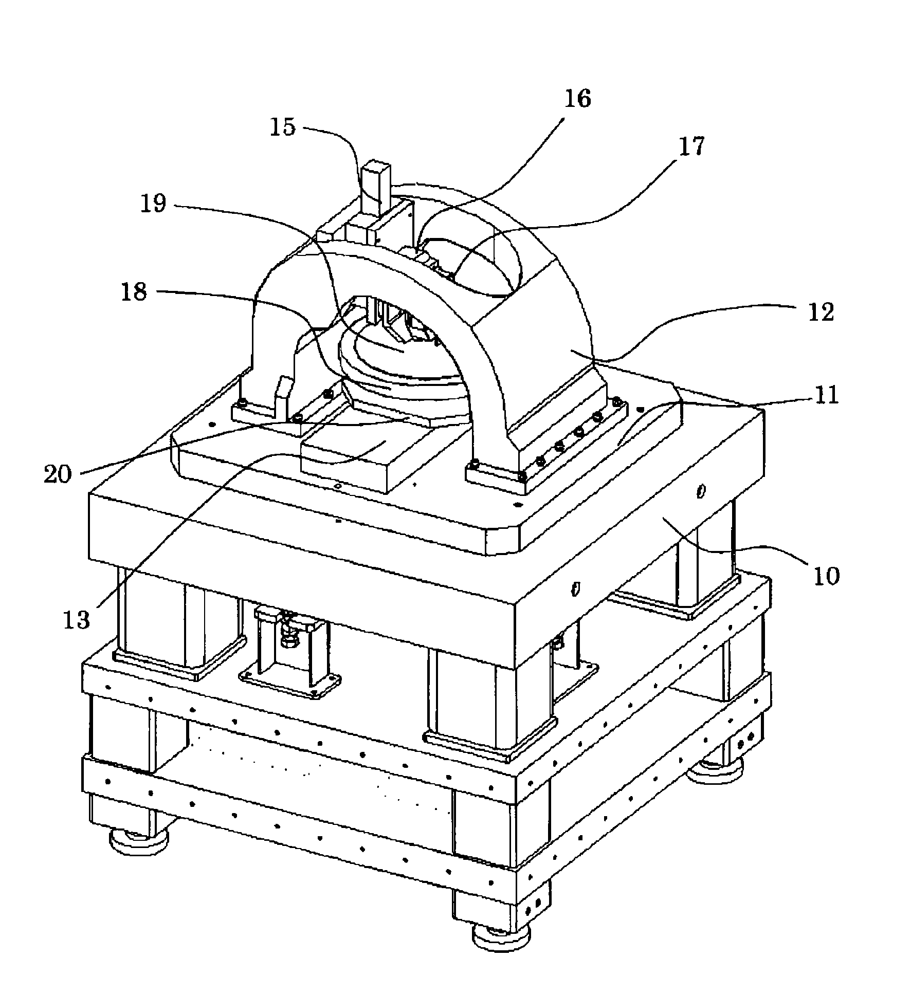
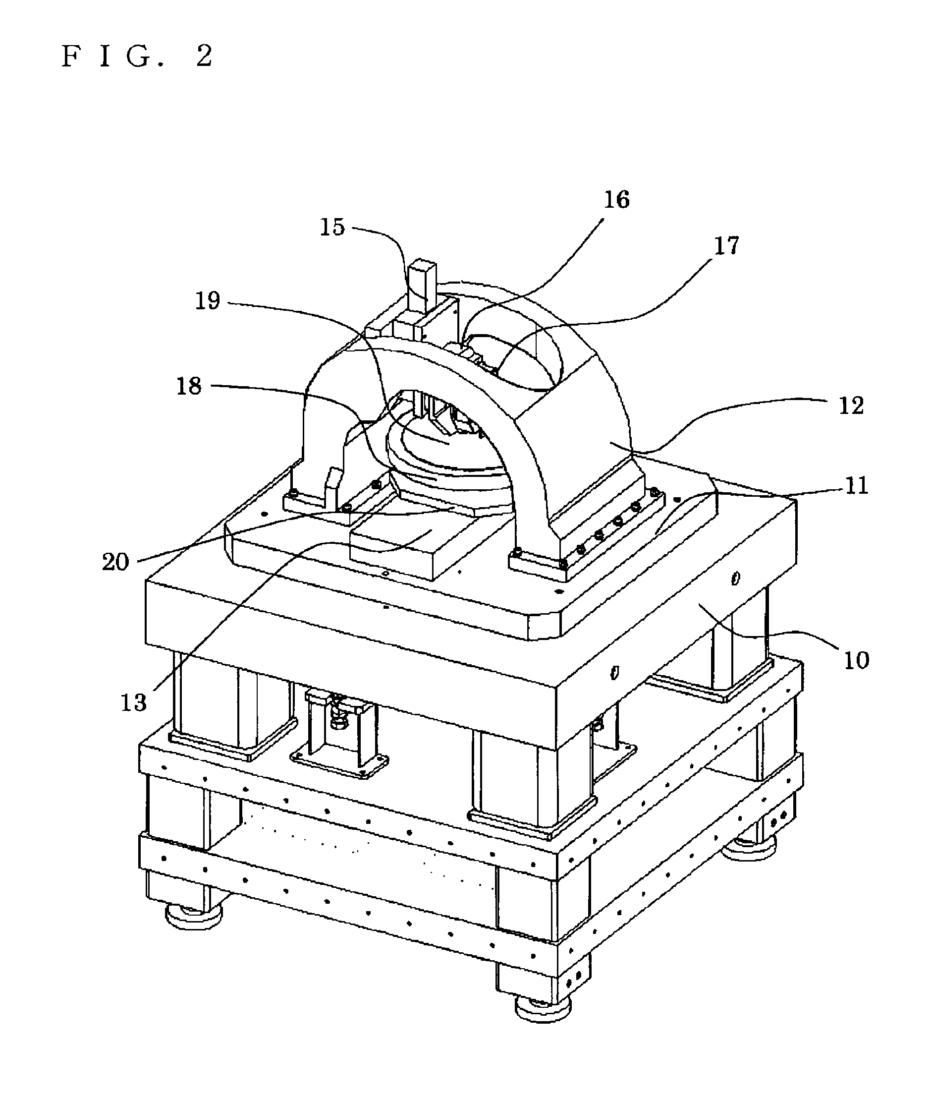
[0022]The support structure member supporting the detection means is formed into the arch shape, the perpendicular surface is formed in the support structure member having the arch shape, and the detection means is supported on the perpendicular surface, thereby reducing a relative shift due to disturbance between the detection means supported by the support structure member and an object to be detected which is opposed to the detection means. As a result, a noise component can be reduced. The curved structure having the arch shape is a structure formed consistent with the catenary curve (catenary), and hence local stress concentration can be avoided to obtain higher rigidity than in a conventional support structure. From the reason described above, it is more preferable to integrally form the support structure member having the arch shape to obtain further higher rigidity. With the apparatus structure according to the present invention, the improvements of resolution and disturbance vibration resistance can be expected as described above. Therefore, the apparatus structure is effective in a case where the detection portion is at least a detection portion for performing analysis, inspection, or measurement on the physical properties or shape of the sample based on any one of electronic principles of optical, magnetic, and electron microscopes. The apparatus structure is also effective for an apparatus including an alignment mechanism for controlling a relative position between the detection portion and the sample located on the sample stage. Therefore, when the apparatus structure is used for a probe microscope whose detection means has a high-sensitive detection portion capable of measuring an atomic structure and physical properties, high-resolution sample analysis or shape measurement can be achieved and noise is reduced to improve the reliability of a result obtained by measurement. Thus, the apparatus structure is particularly effective.

Problems solved by technology

A disturbance vibration causes an increase in contact frequency between the probe and the surface of the sample, and hence it is likely to break the tip end of the probe, thereby causing a reduction in resolution.

Method used


Image

  • Apparatus structure and scanning probe microscope including apparatus structure
  • Apparatus structure and scanning probe microscope including apparatus structure
  • Apparatus structure and scanning probe microscope including apparatus structure

Examples


Embodiment Construction

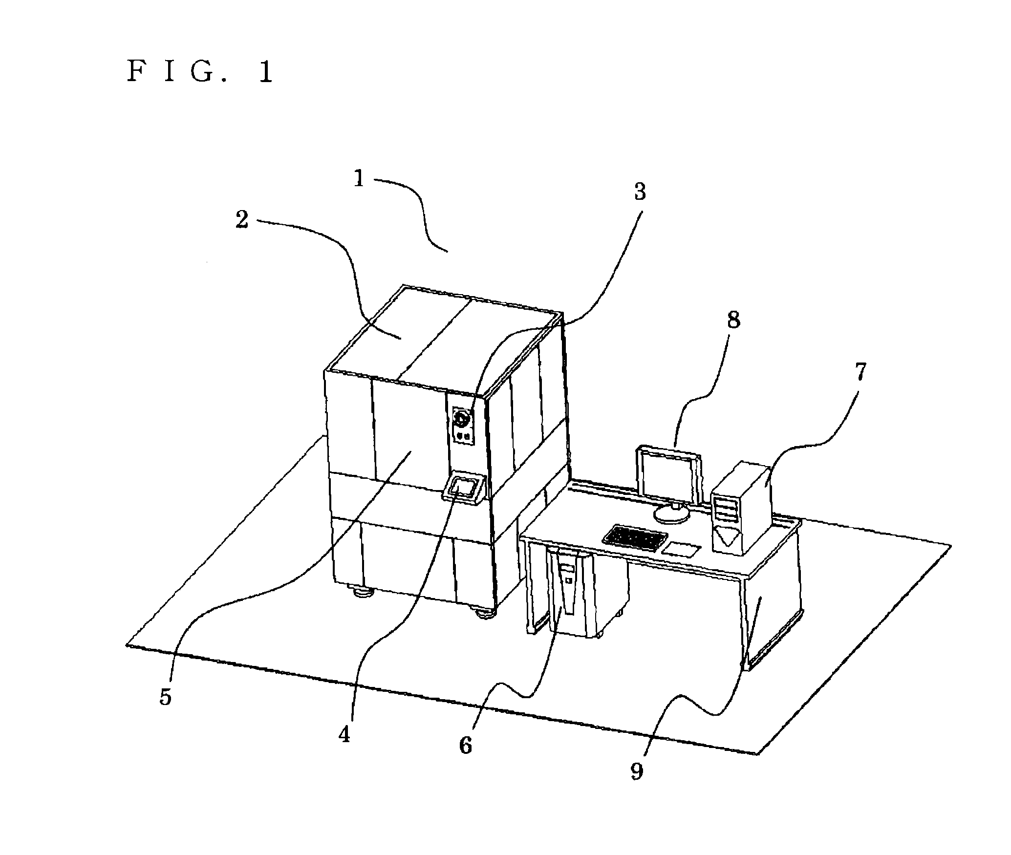
[0035]Hereinafter, an example of an apparatus structure according to a first embodiment of the present invention in a case of a probe microscope is described with reference to FIGS. 1 to 5. In the following embodiment, fundamentally the same structures as the schematic system structure of the probe microscope as illustrated in FIG. 8 are expressed by the same reference numerals and thus the description is omitted here.

[0036]FIG. 1 illustrates a probe microscope apparatus according to the first embodiment of the present invention. A probe microscope unit 1 is covered with an acoustic insulating cover 2 for protecting a probe microscope internal unit from acoustic noise. An operating panel 3 including a system ON / OFF switch and an emergency stop switch, an operating section 4 including a liquid crystal touch panel for instructing a stage operation, and a door 5 for operating the probe microscope internal unit located inside the acoustic insulating cover 2 are provided on the acoustic ...


PUM


Abstract

Provided are a structure of an apparatus for analysis, inspection, and measurement in which a support structure supporting a detection unit is resistant to disturbance, suppresses a reduction in resolution during large-sample measurement, and has high rigidity, and a probe microscope using the apparatus structure. The apparatus structure supporting the detection unit which is opposed to a sample which is located on a unit movable in at least one axis direction and is an object to be analyzed has an arch shape. In the apparatus structure having the arch shape and supporting the detection unit, a surface substantially perpendicular to a flat surface portion of a sample holder located immediately under the apparatus structure is formed. The detection unit is supported on the perpendicular surface. The arch-shaped apparatus structure is a curved structure consistent with a catenary curve.

Description

RELATED APPLICATIONS[0001]This application claims priority under 35 U.S.C. §119 to Japanese Patent Application No. JP2008-096894 filed on Apr. 3, 2008, the entire content of which is hereby incorporated by reference.BACKGROUND OF THE INVENTION[0002]1. Field of the Invention[0003]The present invention relates to a structure of an analysis, inspection, or measurement apparatus including a sample analysis apparatus, a shape measurement apparatus, and a probe microscope for measuring shape information such as surface roughness or a step of a sample surface, or physical information such as a dielectric constant or viscoelasticity.[0004]2. Description of the Related Art[0005]In recent years, a probe microscope including an atomic force microscope (AFM) with atomic resolution has been expected for shape measurement to evaluate a fine shape. The atomic force microscope which is a type of probe microscope has been expected as means for observing a surface shape of a novel insulating material...

Claims


Application Information

Patent Timeline
Patent Type & Authority Patents(United States)
IPC IPC(8): G01Q60/16G01Q60/00
CPCG01Q70/04B82Y35/00
Inventor WAKIYAMA, SHIGERUAKAMATSU, KENICHI
Owner HITACHI HIGH TECH SCI CORP
Learn More