Connecting device

a technology of connecting device and metal, which is applied in the direction of snap fasteners, buckles, mechanical devices, etc., can solve the problems of difficult to eliminate the frictional sound offensive to the ear generated between the metal and the three components, and the assembly is difficult. to achieve the effect of excellent appearan

Inactive Publication Date: 2011-05-24
YKK CORP
View PDF17 Cites 3 Cited by
  • Summary
  • Abstract
  • Description
  • Claims
  • Application Information

AI Technical Summary

Benefits of technology

[0010]An object of the invention is to provide a connecting device which is easy to assemble and whose engagement head is not exposed outside, the connecting device preventing occurrence of frictional sound when a connecting device main body is rotated with respect to a belt attaching member and presenting a beautiful appearance.
[0016]In any case, after the connecting device is assembled, the engagement head is accommodated in an accommodating space within the cylindrical wall portion of the ring-like member. Consequently, the engagement head is never exposed on the outside face from the cylindrical wall portion, that is, also never exposed outside from the through hole in the belt attaching member, thereby presenting an excellent appearance. By interposing the ring-like member between the connecting device main body and the large-diameter hole portion of the belt attaching member, each material can be selected appropriately depending on the function, thereby meeting diversified demands. Further, since the outside diameter of the cylindrical wall portion of the ring-like member is substantially equal to the inside diameter of the large-diameter hole portion in the belt attachment portion, for example, when the ring-like member is accommodated in the large-diameter hole portion with the engaging portion of the ring-like member set down, the ring-like member can be inserted in a stable condition because the inner wall surface of the large-diameter hole portion serves as a guide face. After accommodated in the large-diameter hole portion, the engaging portion of the ring-like member is placed on the stepped portion between the large-diameter hole portion and the small-diameter hole portion, so that the engagement head of the connecting device main body can maintain its posture in a stable state, thereby executing a secure assembly.
[0017]In the invention, if the inside diameter of the engaging portion of the ring-like member is set equal to the inside diameter of the small-diameter hole portion in the belt attaching member, the engagement head of the connecting device main body can be easily inserted into the opening in the ring-like member. In a case where the ring-like member has a plurality of ribs extending from the center of the ring-like member toward the inner peripheral surface of the wall portion, reinforcement of the ring-like member toward a central direction and maintenance of the shape of the ring-like member are achieved, and there is such an effect that deformation of the large-diameter hole portion of the through hole, in which the ring-like member is accommodated, is prevented.
[0018]The height of the ring-like member is substantially equal to the height of the large-diameter hole portion and the height of the engagement head is not larger than the height of the wall portion. For this reason, only by accommodating the ring-like member in the large-diameter hole portion and placing the surface of the ring-like member on a flat plate, the ring-like member can be accommodated in the large-diameter hole portion securely. When the assembly is executed in this state, the engagement head is never exposed outside because the height of the engagement head is not larger than the height of the wall portion, thereby facilitating the assembly.

Problems solved by technology

However, it is troublesome to assemble the three components because no large-diameter hole portion is formed unlike JP-Y-62-27701, and the engagement head is exposed outside, thereby not presenting a good appearance.
Although the ring-like opening member is disposed mainly to absorb a shock, it is difficult to eliminate the frictional sound offensive to the ear generated between the metal and the elastic material such as rubber when the metallic swivel hook main body is rotated with respect to the belt attaching member unless any special processing is executed.

Method used


Image

  • Connecting device
  • Connecting device
  • Connecting device

Examples


first embodiment

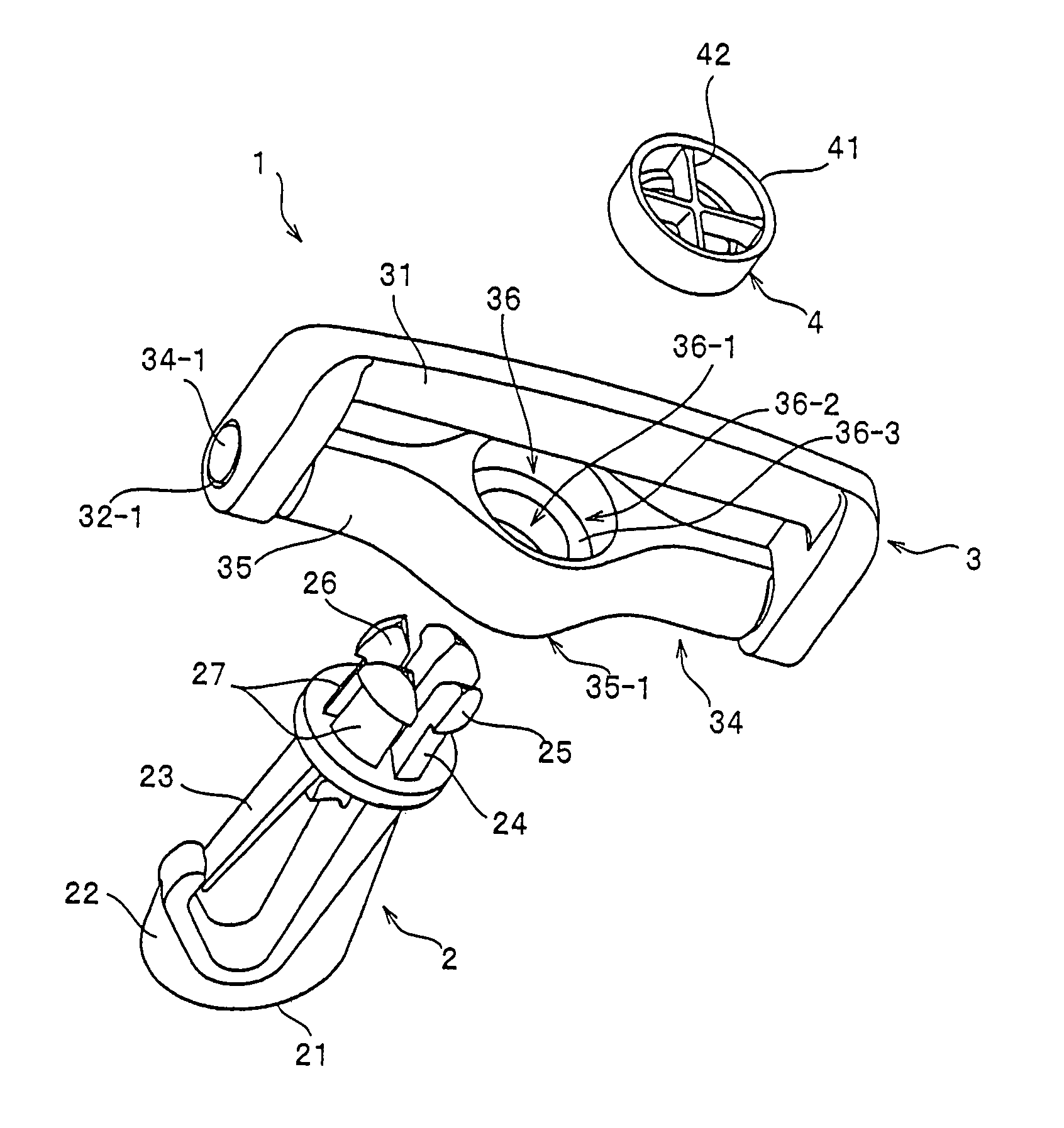
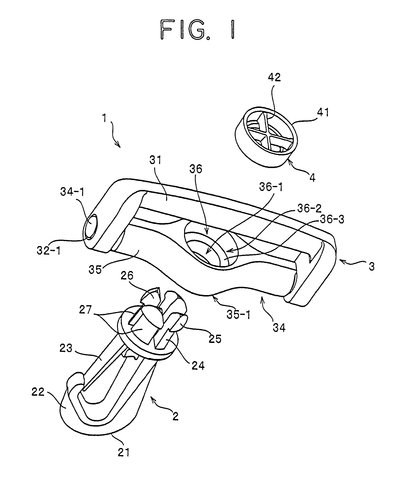
[0026]FIG. 1 is a perspective view of a swivel hook which is a representative example of a connecting device according to a first embodiment of the invention, in which respective components of a swivel hook are disassembled. FIG. 2 is a partially cut enlarged perspective view showing a ring-like member of the swivel hook. FIG. 3 is a partially broken enlarged front view of the components of the swivel hook. FIG. 4 is a partially broken front view of major portions showing the assembled swivel hook. FIG. 5 is a sectional view taken along the line V-V of FIG. 4. In the following description, a direction from an engagement head 25 to a hook portion 22 in a swivel hook main body 2 shown in FIG. 1 is a downward direction and a right-left direction along a longitudinal direction of the belt attaching member 3 is the right-left direction.

[0027]A swivel hook 1 of the invention comprises the swivel hook main body 2 as a connecting device main body, a belt attaching member 3 to be attached to...

second embodiment

[0042]Next, a buckle 5 as a connecting device according to a second embodiment of the invention will be described. In the description of the second embodiment described below, the same reference numerals and names are used for components having the same configuration as the first embodiment. For the reason, detailed description of those components is omitted. Here, FIG. 6 is a perspective view showing the buckle 5 of the second embodiment.

[0043]The buckle 5 according to the second embodiment comprises a buckle main body 50 having a male member 51 and a female member 54 which engages the male member 51 and a belt attaching member 3 which is supported rotatably by the buckle main body 50. The female member 54 has a neck portion 24 and an engagement head 25 which is expanded in an outward direction from the center of the axis line such that the diameter of the engagement head 25 can be reduced at the front end of the neck portion 24. The male member 51 is inserted into a female member ...


PUM


Abstract

A connecting device which has an excellent appearance, produces no frictional sound between a connecting device main body such as a swivel hook main body and a belt attaching member and can be assembled easily and securely. The connecting device includes a neck portion standing from a proximal portion of a main body of the connecting device and an engagement head which is expanded in an outward direction form a center of an axis line such that a diameter thereof can be reduced, the engagement head being provided at a front end of the neck portion. A belt attaching member is connected to the main body rotatably around the neck portion. A through hole which the engagement head can be engaged with by insertion is formed in part of the belt attaching member. In the through hole, a small-diameter hole portion having a smaller diameter than the diameter of the engagement head and a large-diameter hole portion having a large diameter than the diameter of the engagement head are connected via a stepped portion. The large-diameter hole portion has a ring-like member which allows the neck portion to be inserted therethrough. The ring-like member has a cylindrical wall portion which is accommodated in the large-diameter hole portion and a ring-like engaging portion provided at an end of the wall portion and extended toward a center thereof. An inside diameter of the engaging portion is equal to an outside diameter of the diameter of the engagement head when it is reduced.

Description

BACKGROUND OF THE INVENTION[0001]1. Field of the Invention[0002]The invention relates to a connecting device, such as a swivel hook made of a synthetic resin, which can be easily connected to a stopper attached to a bag such as a shoulder bag or a knapsack by hooking or a buckle made of a synthetic resin for use in connecting or disconnecting both ends of a single belt or two belts, and more particularly, to a connecting device in which a belt attaching member and a connecting device main body are rotatable with respect to each other.[0003]2. Description of Related Art[0004]Conventionally, a swivel hook which is one of connecting devices, in which a hook-like swivel hook main body and a belt attaching member are connected rotatably to each other, have been put to practical use as disclosed in, for example, Japanese Utility Model Application Publication (JP-Y) No. 62-27701 and U.S. Pat. No. 6,286,190.[0005]The swivel hook of JP-Y-62-27701 has a swivel hook main body and a belt attach...

Claims


Application Information

Patent Timeline
Patent Type & Authority Patents(United States)
IPC IPC(8): A44B11/25
CPCA44B11/266A44B11/28F16B21/088F16B45/02F16G15/08Y10T24/47Y10T24/45241Y10T24/4755Y10T24/45581Y10T24/45419F16B45/036
Inventor UEHARA, RYOICHIRO
Owner YKK CORP
Why Eureka
Try Eureka