Inductively-driven plasma light source

a plasma light source and inductive drive technology, applied in gas-filled discharge tubes, electric discharge lamps, solid cathodes, etc., can solve the problems of undesirable particle emission of plasma light sources from electrodes, and achieve the effects of minimizing emissions, reducing indirect or direct plasma emissions, and maximizing collisions with emissions

Active Publication Date: 2011-05-24
HAMAMATSU PHOTONICS KK
View PDF67 Cites 43 Cited by
  • Summary
  • Abstract
  • Description
  • Claims
  • Application Information

AI Technical Summary

Benefits of technology

[0046]The invention, in another aspect, features a light source. The light source includes a chamber having a plasma discharge region and containing an ionizable medium. The light source also includes a magnetic core that surrounds a portion of the plasma discharge region. The light source also includes a power system for providing energy to the magnetic core for delivering power to a plasma formed in the plasma discharge region, wherein the plasma has a localized high intensity zone. The light source also includes a filter disposed relative to the light source to reduce indirect or direct plasma emissions.
[0047]The filter can be configured to maximize collisions with emissions which are not traveling parallel to radiation emanating from the light source (e.g., from the high intensity zone). The filter can be configured to minimize reduction of emissions traveling parallel to radiation emanating from the light source (e.g., from the high intensity zone). In one embodiment, the filter is made up of walls which are substantially parallel to the direction of radiation emanating from the high intensity zone, and has channels between the walls. A curtain of gas can be maintained in the vicinity of the filter to increase collisions between the filter and emissions other than radiation.
[0050]In one embodiment, the method includes positioning the filter relative to the high intensity zone (e.g., a source of light) to reduce direct or indirect emissions. The method can include maximizing collisions with emissions which are not traveling parallel to radiation emanating from the high intensity zone. The method can include minimizing reduction of emissions traveling parallel to the radiation emanating from the high intensity zone.

Problems solved by technology

As a result, however, the plasma light sources generate undesirable particle emissions from the electrodes.

Method used


Image

  • Inductively-driven plasma light source
  • Inductively-driven plasma light source
  • Inductively-driven plasma light source

Examples


Embodiment Construction

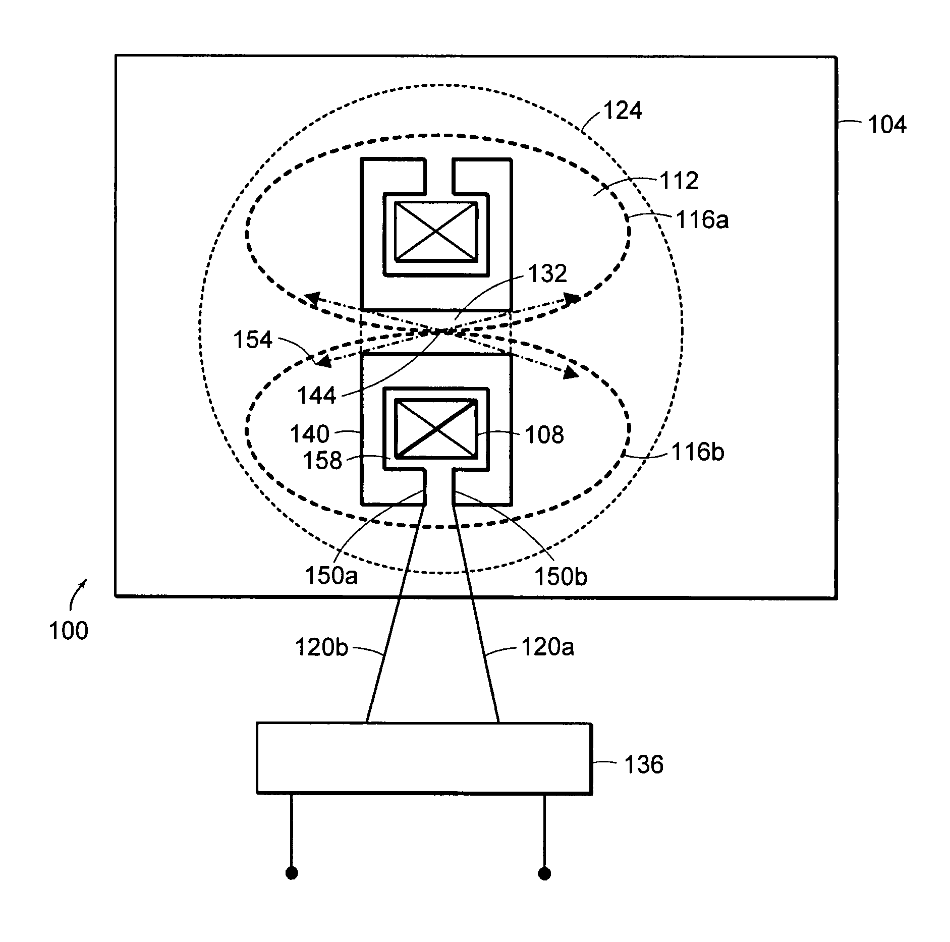
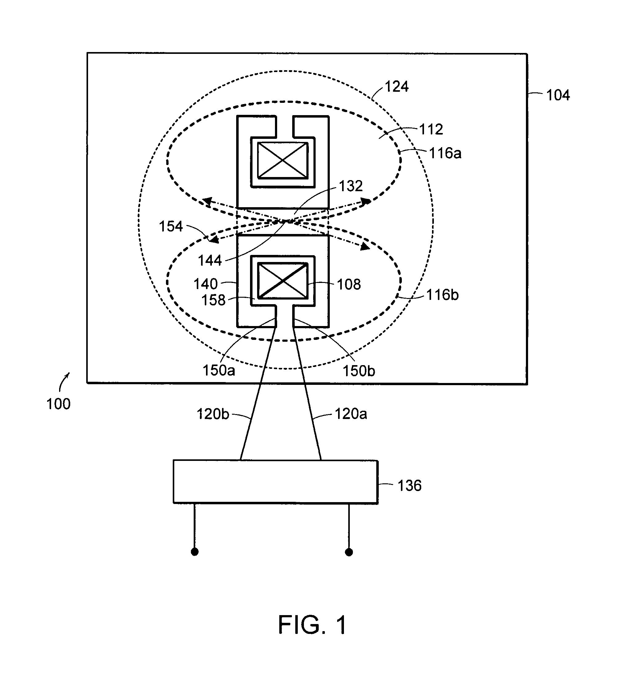
[0113]FIG. 1 is a cross-sectional view of a plasma source 100 for generating a plasma that embodies the invention. The plasma source 100 includes a chamber 104 that defines a plasma discharge region 112. The chamber 104 contains an ionizable medium that is used to generate a plasma (shown as two plasma loops 116a and 116b) in the plasma discharge region 112. The plasma source 100 includes a transformer 124 that induces an electric current into the two plasma loops 116a and 116b (generally 116) formed in the plasma discharge region 112. The plasma loops collectively form the secondary circuit of a transformer. The transformer 124 includes a magnetic core 108 and a primary winding 140. A gap 158 is located between the winding 140 and the magnetic core 108.

[0114]In this embodiment, the winding 140 is a copper enclosure that at least partially encloses the magnetic core 108 and that provides a conductive path that at least partially encircles the magnetic core 108. The copper enclosure ...


PUM


Abstract

An apparatus for producing light includes a chamber that has a plasma discharge region and that contains an ionizable medium. The apparatus also includes a magnetic core that surrounds a portion of the plasma discharge region. The apparatus also includes a pulse power system for providing at least one pulse of energy to the magnetic core for delivering power to a plasma formed in the plasma discharge region that forms a secondary circuit of a transformer. The plasma has a localized high intensity zone.

Description

RELATED APPLICATIONS[0001]This application is a continuation-in-part of U.S. Ser. No. 11 / 176, 015, filed on Jul. 7, 2005, which is a continuation-in-part of U.S. Ser. Nos. 10 / 888,434, 10 / 888,795 and 10 / 888,955, all filed on Jul. 9, 2004. This application claims priority to and incorporates by reference in their entirety U.S. Ser. Nos. 11 / 176,015, 10 / 888,434, 10 / 888,795 and 10 / 888,955.FIELD OF THE INVENTION[0002]The invention relates to methods and apparatus for generating a plasma, and more particularly, to methods and apparatus for providing an inductively-driven plasma light source.BACKGROUND OF THE INVENTION[0003]Plasma discharges can be used in a variety of applications. For example, a plasma discharge can be used to excite gases to produce activated gases containing ions, free radicals, atoms and molecules. Plasma discharges also can be used to produce electromagnetic radiation (e.g., light). The electromagnetic radiation produced as a result of a plasma discharge can itself be...

Claims


Application Information

Patent Timeline
Patent Type & Authority Patents(United States)
IPC IPC(8): H05B31/26
CPCH05G2/005H05G2/003
Inventor SMITH, DONALD K.HORNE, STEPHEN F.BESEN, MATTHEW M.BLACKBOROW, PAUL A.COLLINS, RON
Owner HAMAMATSU PHOTONICS KK
Why Eureka
Try Eureka