System and apparatus for removably mounting hard disk drives

a hard disk drive and mounting system technology, applied in the direction of electrical apparatus construction details, instruments, casings/cabinets/drawers, etc., can solve the problems of difficult to utilize hard disk storage devices not specifically designed for use within a 5.25 inch device form factor, and typically unsuitable bays

Active Publication Date: 2011-05-24
AMERICAN MEGATRENDS
View PDF27 Cites 9 Cited by
  • Summary
  • Abstract
  • Description
  • Claims
  • Application Information

AI Technical Summary

Benefits of technology

In one implementation, the disk drive carrier rails are constructed from a light transmissive material and have a front, back, and side surfaces. The disk drive carrier rails are symmetric so that they may be installed along the top or bottom of the disk drive carrier cage. In one implementation, the disk drive backplane further includes light emitting devices for transmitting light from the disk drive backplane to the front surface of the disk drive carrier rails when installed in the disk drive carrier cage. For instance, disk drive carrier rails may be mounted along the top of the disk drive carrier cage and along the bottom of the disk drive carrier cage. Lights on the disk drive backplane can be illuminated to enable quick identification of the corresponding location within the disk drive carrier cage even when a disk drive carrier is not present.

Problems solved by technology

These bays are typically unsuited for holding storage devices that are not specifically intended to be utilized within a 5.25 inch device form factor.
As an example, it is generally difficult to utilize hard disk storage devices not specifically designed for use within a 5.25 inch device form factor, such as 2.5 inch hard disk drives, within the space previously utilized for 5.25 inch optical mass storage devices.

Method used


Image

  • System and apparatus for removably mounting hard disk drives
  • System and apparatus for removably mounting hard disk drives
  • System and apparatus for removably mounting hard disk drives

Examples


Embodiment Construction

Embodiments described herein provide apparatus and systems for removably mounting mass storage devices within a computer system. In the following detailed description, references are made to the accompanying drawings that form a part hereof, and in which are shown by way of illustration specific embodiments or examples. Referring now to the drawings, in which like numerals represent like elements throughout the several figures, several illustrative implementations will be described.

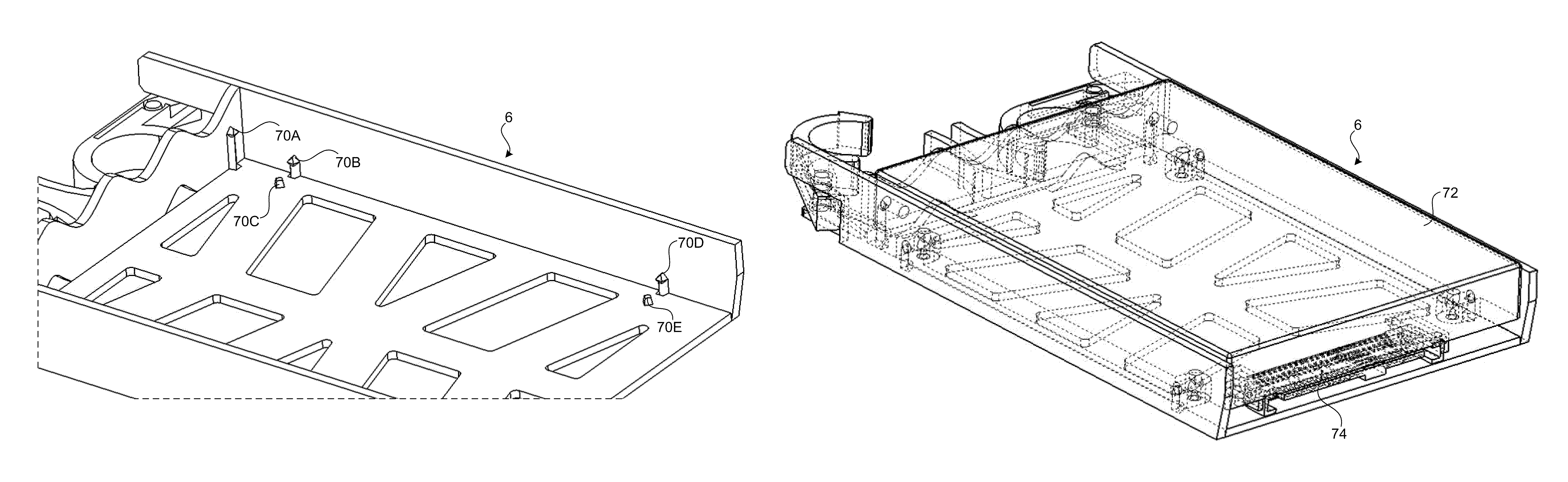
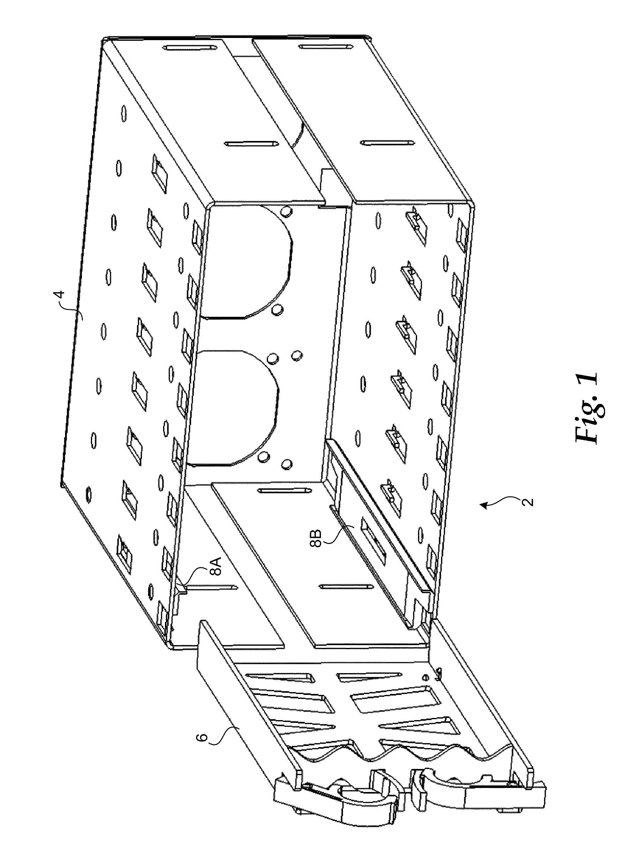
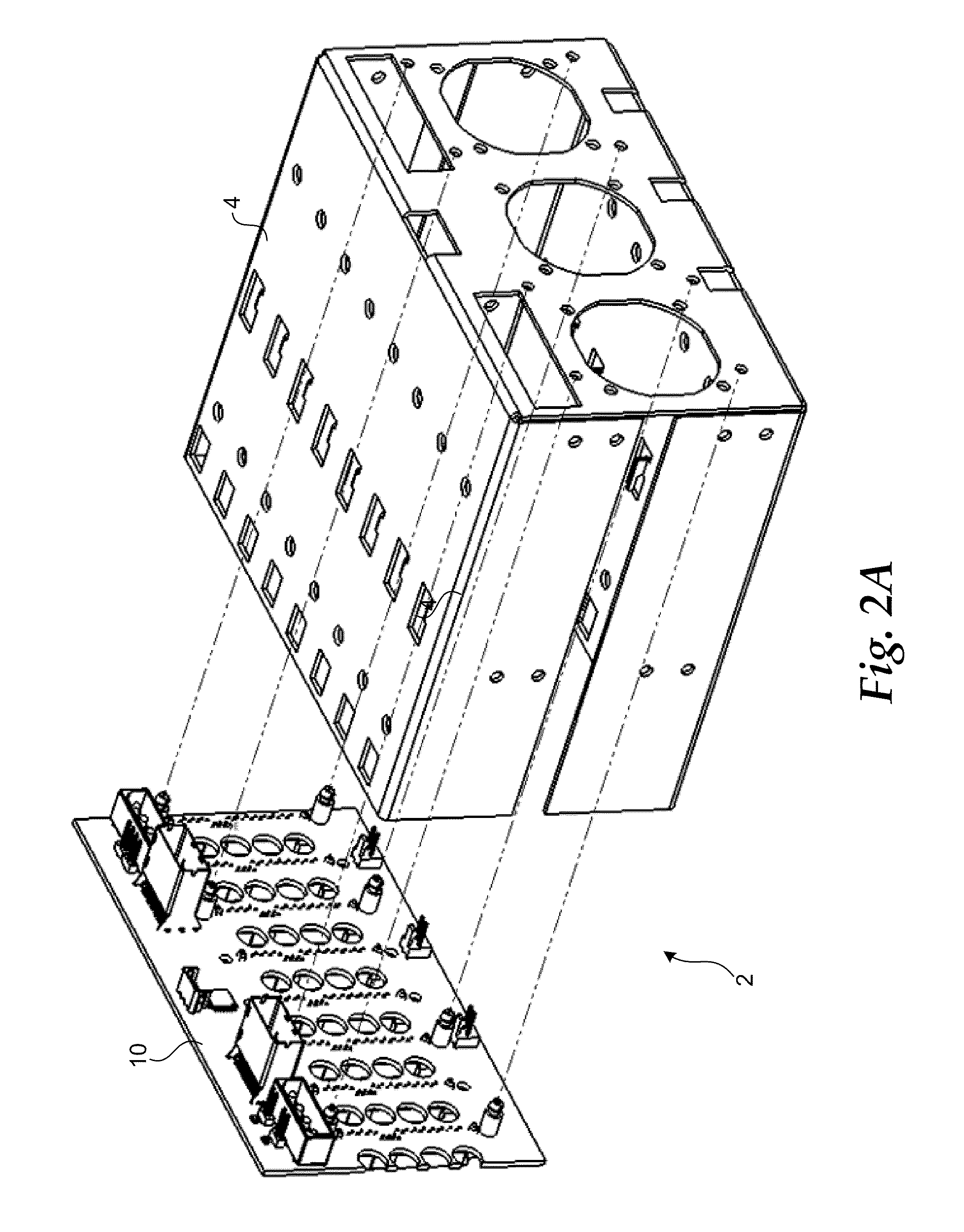
FIG. 1 shows a perspective view of a system for removably mounting one or more hard disk drives within a computer system. In particular, according to one implementation, the system 2 includes a disk drive carrier cage 4, one or more disk drive carriers 6 each capable of holding a single hard disk drive, and as many as sixteen disk drive carrier rails 8. As illustrated in FIG. 1, the disk drive carrier rails 8 are mountable within the disk drive carrier cage 4. When inserted therein, the disk drive carrier...


PUM


Abstract

A system and apparatus are described for removably mounting one or more hard disk drives within a computer system. According to one embodiment, the system includes a disk drive carrier cage configured to receive a disk drive backplane and up to eight pair of disk drive carrier rails. The disk drive carrier cage is sized for insertion into a drive bay having the dimensions of two optical mass storage devices compatible with a 5.25 inch form factor. The system also includes a disk drive backplane for receiving up to eight hard disk drives, disk drive carriers for holding the hard disk drives, and disk drive carrier rails mountable within the disk drive carrier cage for slidably receiving the disk drive carriers. The disk drive carriers and disk drive carrier rails are translucent thereby permitting light emanating from the backplane to be viewed at the front of the cage.

Description

BACKGROUNDComputer system cases come in a wide variety of sizes and shapes. Typical case form factors include desktop and tower cases. Cases such as these typically offer some capacity for expansion. In particular, many cases include three or more 5.25 inch drive bays. Typically, these bays are utilized to hold optical mass storage devices, such as compact disk (“CD”) read-only memory (“CD-ROM”) devices, digital versatile disc (“DVD”) devices, CD or DVD recording devices (such as CD-R or DVD-R devices), or other types of optical mass storage devices.In the past, computer systems have often been configured with multiple optical mass storage devices. For instance, a computer may be configured with a CD-ROM drive, a DVD playback drive, and a CD or DVD recording device. However, with the advent of multifunction optical mass storage devices, the need for multiple devices has generally been eliminated. As an example, where it was once necessary to include both a recordable CD device and a...

Claims


Application Information

Patent Timeline
Patent Type & Authority Patents(United States)
IPC IPC(8): G06F1/16H05K5/00H05K7/00
CPCG11B33/125G06F1/187
Inventor SIVERTSEN, CLAS GERHARD
Owner AMERICAN MEGATRENDS
Why Eureka
Try Eureka