Power-driven torque intensifier

a torque intensifier and torque technology, applied in the direction of power driven tools, wrenches, metal-working apparatuses, etc., can solve the problems of reducing the speed, and the accuracy of torque power tools, so as to reduce the speed, the speed is not very accurate and very slow

Active Publication Date: 2011-05-31
UNAX CORP
View PDF38 Cites 57 Cited by
  • Summary
  • Abstract
  • Description
  • Claims
  • Application Information

AI Technical Summary

Benefits of technology

[0009]Accordingly, it is an object of the present invention to provide a torque intensifying tool which eliminates the disadvantage of the prior art.
[0010]The torque intensifying tool in accordance with the present invention is based on the idea to stop the usual equal, simultaneous but opposite turning of action and reaction when high nut turning speed is required so as to avoid that almost all turning parts require bearings.

Problems solved by technology

The usual impact wrenches, which provide a high run down and run off speed, have the disadvantage that they are not very accurate and very slow once the nut hits the flange face.
Torque power tools are torque accurate, but relatively slow in run up and run down of fasteners.
Yet, still they are faster than impact guns once the nut is turned on the flange face.
It turns gears, which reduce the speed but increases the relatively low torque output of the motor.
The higher the torque, the larger the gear ratio and obviously the slower the speed with which the nut is turned.
It is known that running a nut down takes usually less torque than running it off due to possible thread corrosion when loosening a nut.
None provides a run down or run off speed where the entire gear housing together with the inner gear assembly and the output drive turn at the same high speed in the same direction.
There is, however, none in the market where a push onto the fastener changes from turning the gear housing, its gears and its output shaft in the same direction at the same speed to applying a turning force to the gears and the output shaft in one direction and simultaneously an opposite turning force to the gear housing.
The problem with that is that a high speed, the gears and the output shaft turn so fast in the gear housing that almost all turning parts require bearings, which makes the tool larger and heavier.

Method used


Image

  • Power-driven torque intensifier
  • Power-driven torque intensifier
  • Power-driven torque intensifier

Examples


Embodiment Construction

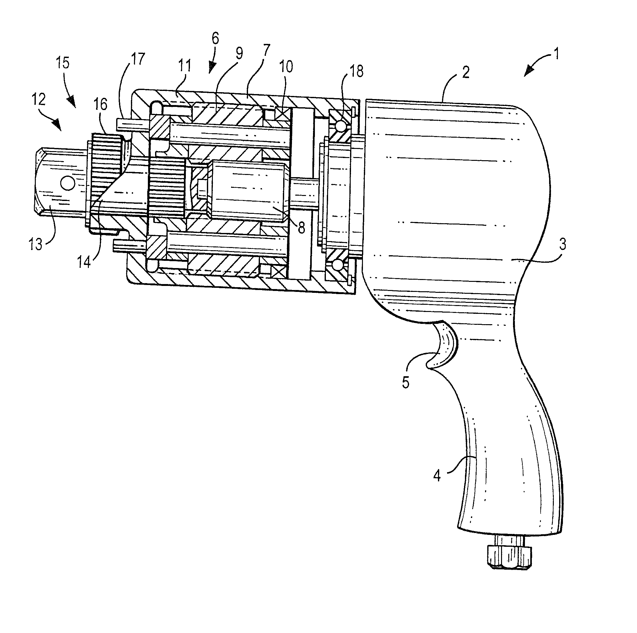
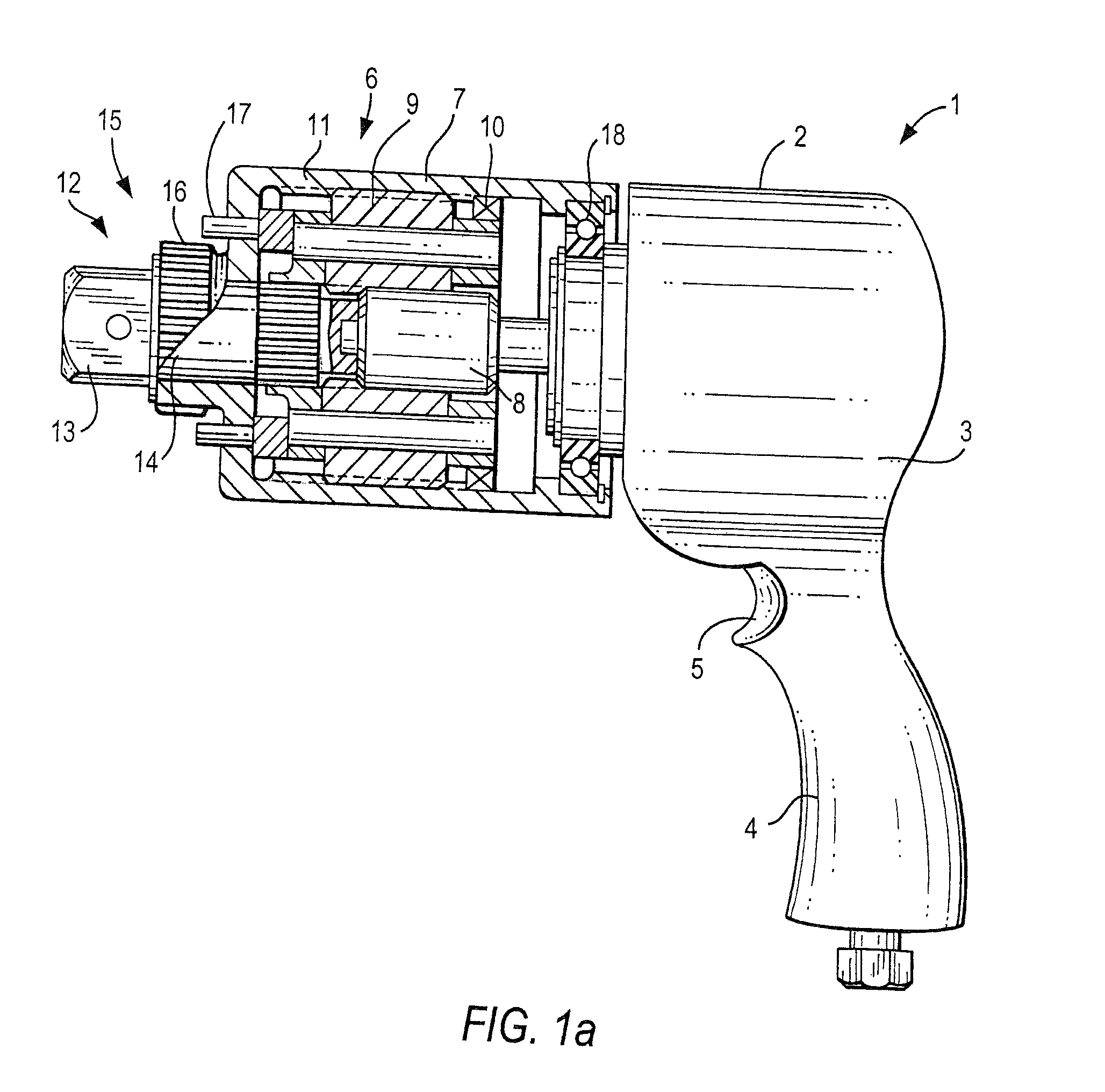
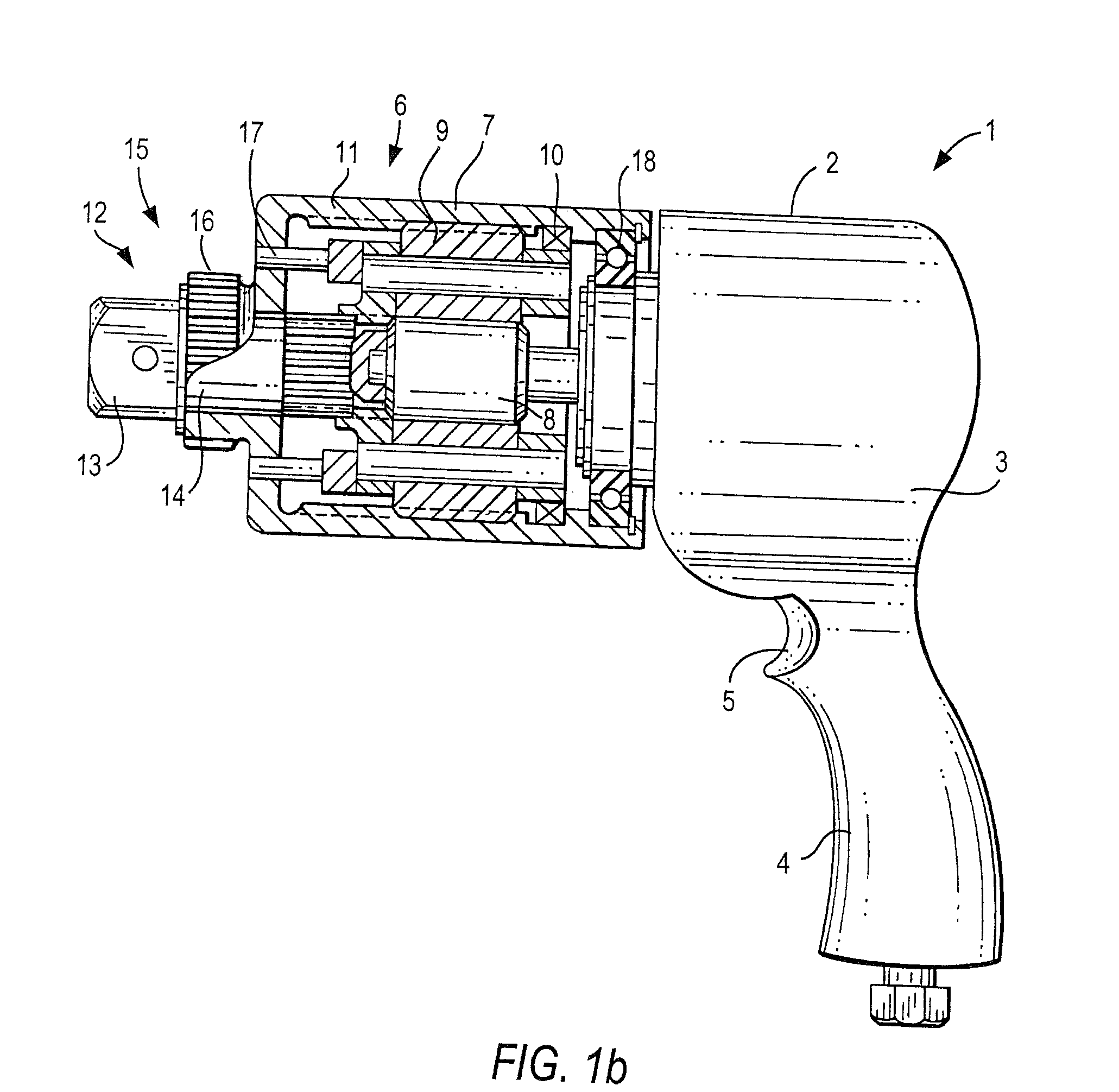
[0020]A torque intensifying tool for tightening and loosening threaded connectors has drive means which are identified as a whole with reference numeral 1. The drive means 1 can have a drive housing 2 and a drive which is identified with reference numeral 3. The drive means 1 can be formed as a motor drive means, in which case it can include a motor. It is also possible that the drive means 1 is formed as manual drive means, for example as a torque wrench. The drive means 1 generate a torque which is to be transmitted for operation. In the embodiment shown in FIGS. 1a, 1b the drive housing 2 has a handle 4 which is to be held by an operator and provided with switching means 5 for switching the drive means between an inoperative position and an operative position.

[0021]The torque intensifying tool in accordance with the present invention further has at least one torque intensifier means which are identified as a whole with reference numeral 6. The torque intensifier means 6 have a to...


PUM


Abstract

A torque intensifying tool for tightening and loosening threaded connectors has at least one torque intensifier unit with a torque intensifier housing portion, an input and a first output and a second output, a drive connected with the input unit for transmitting a torque from the drive through the intensifying unit to a threaded connector, so that in one mode of operation the housing portion together with the first and the second outputs turn in the same direction, and in another mode of operation the housing portion together with one of the first and second outputs receives a turning force in one direction while the other one of the first and second outputs receives an equal turning force in the opposite direction, and so that one of the first and second output means turns in the one mode and in the another mode while the other of the first and second output means turns in the one mode and reacts in the another mode.

Description

CONTINUATION-IN-PART APPLICATION[0001]This is a continuation-in-part application of application Ser. No. 11 / 414,702 filed on Apr. 28, 2006 now abandoned.BACKGROUND OF THE INVENTION[0002]The present invention relates to a torque intensifying tool.[0003]In tightening fasteners, once the nut hits the flange surface the turning degree to tighten it up is very little. What the customer wants, on the other hand, is high turning speed so that a nut can be run down or off very fast.[0004]The usual impact wrenches, which provide a high run down and run off speed, have the disadvantage that they are not very accurate and very slow once the nut hits the flange face. Torque power tools are torque accurate, but relatively slow in run up and run down of fasteners. Yet, still they are faster than impact guns once the nut is turned on the flange face. Torque power tools usually have an air, electric or hydraulic motor. It turns gears, which reduce the speed but increases the relatively low torque o...

Claims


Application Information

Patent Timeline
Patent Type & Authority Patents(United States)
IPC IPC(8): B25B21/00B25B13/48B25B17/02
CPCB25B13/488B25B23/0078B25B21/002B25B21/00B23P19/065B25B21/008B25F5/001B25B23/00B25B23/147
Inventor JUNKERS, JOHN KKOPPENHOEFER, PETERVOICU, CALINSMITH, NEILKIM, EDWARD
Owner UNAX CORP
Why Eureka
Try Eureka