Media stacker

a technology of media stacker and stacked tines, which is applied in the directions of thin material handling, article delivery, transportation and packaging, etc., can solve the problems of media item crumples and jams of the stacker unit, and achieve the effect of reducing time and enlarger the gap between adjacent tines

Active Publication Date: 2011-05-31
NCR CORP
View PDF9 Cites 4 Cited by
  • Summary
  • Abstract
  • Description
  • Claims
  • Application Information

AI Technical Summary

Benefits of technology

[0011]According to a first aspect there is provided a media stacker unit comprising: (i) at least one stacker wheel including: a hub for mounting on an axle, and a plurality of arcuate tines, each tine being coupled to the hub at a hub end and extending transverse to the axle to a point radially distal from the axle at a capture end so that when the stacker wheel is rotated about the axle the capture ends define a capture circumference, each tine further comprising a resilient tine portion; and (ii) a detent partially extending within the capture circumference for engaging with and temporarily retarding successive capture ends as the stacker wheel is rotated to reduce the time during which each capture end blocks a media transport path.
[0015]Suitable materials for the capture end of the arcuate tines include polyoxymethylene and polyamide, due to their hard-wearing, low friction properties. The entire stacker wheel may be composed of the same material, for example, polyoxymethylene or polyamide. The entire stacker wheel may be stamped from a polyamide sheet.
[0019]By virtue of this aspect, successive capture ends of the arcuate tines are held back temporarily and then released so that each released capture end accelerates through a media item input zone, thereby reducing the time during which a capture end blocks the input zone. This reduces the possibility of a media item colliding with a released capture end. In effect, this enlarges the gap between adjacent tines at the input zone by reducing the gap between adjacent tines immediately before the input zone.

Problems solved by technology

One problem associated with a stacker unit is that it is possible for a media item to collide with the end of a tine of a stacker wheel, so that the media item crumples and jams the stacker unit instead of entering the stacker unit.

Method used


Image

  • Media stacker
  • Media stacker
  • Media stacker

Examples


Embodiment Construction

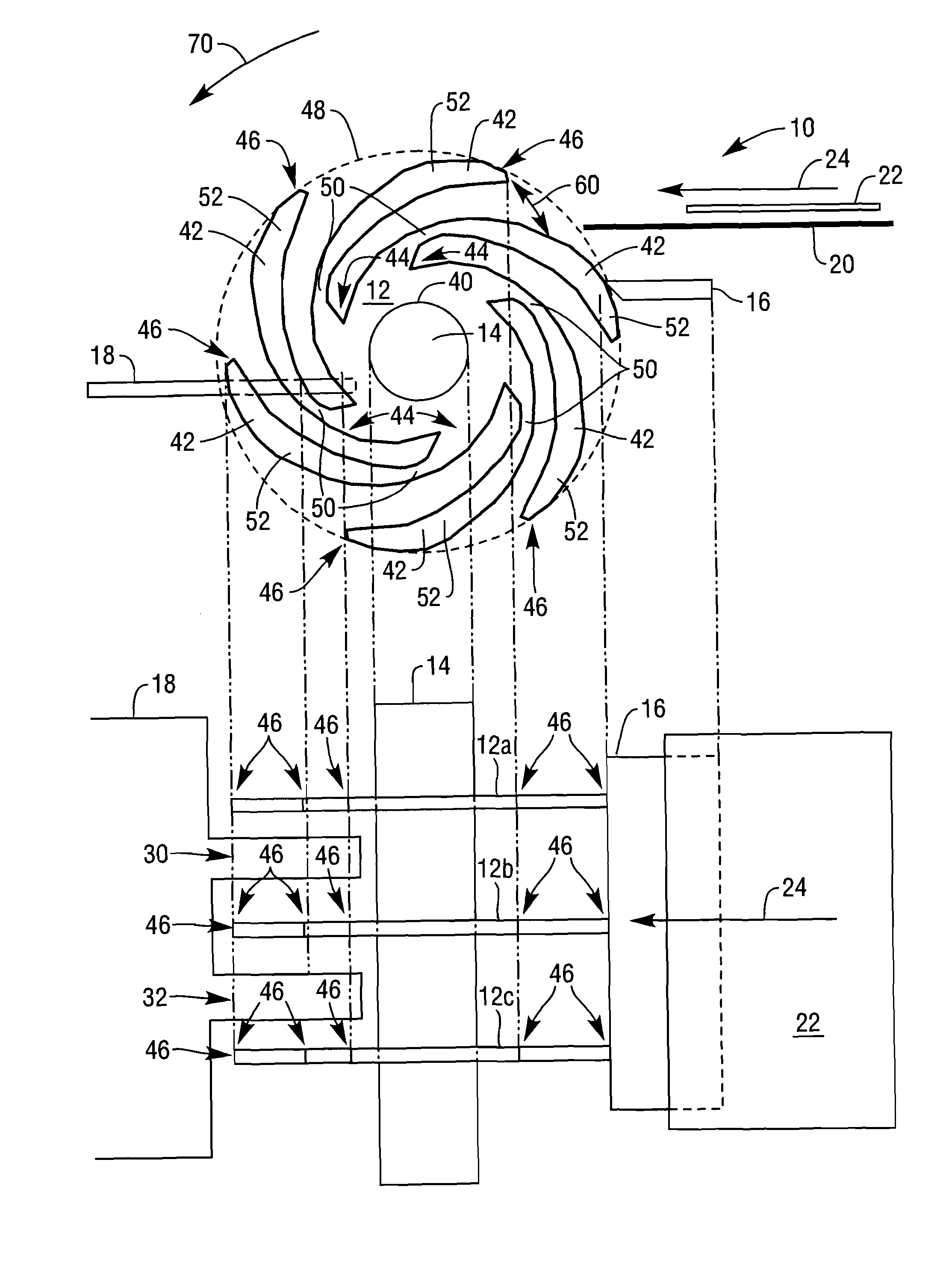
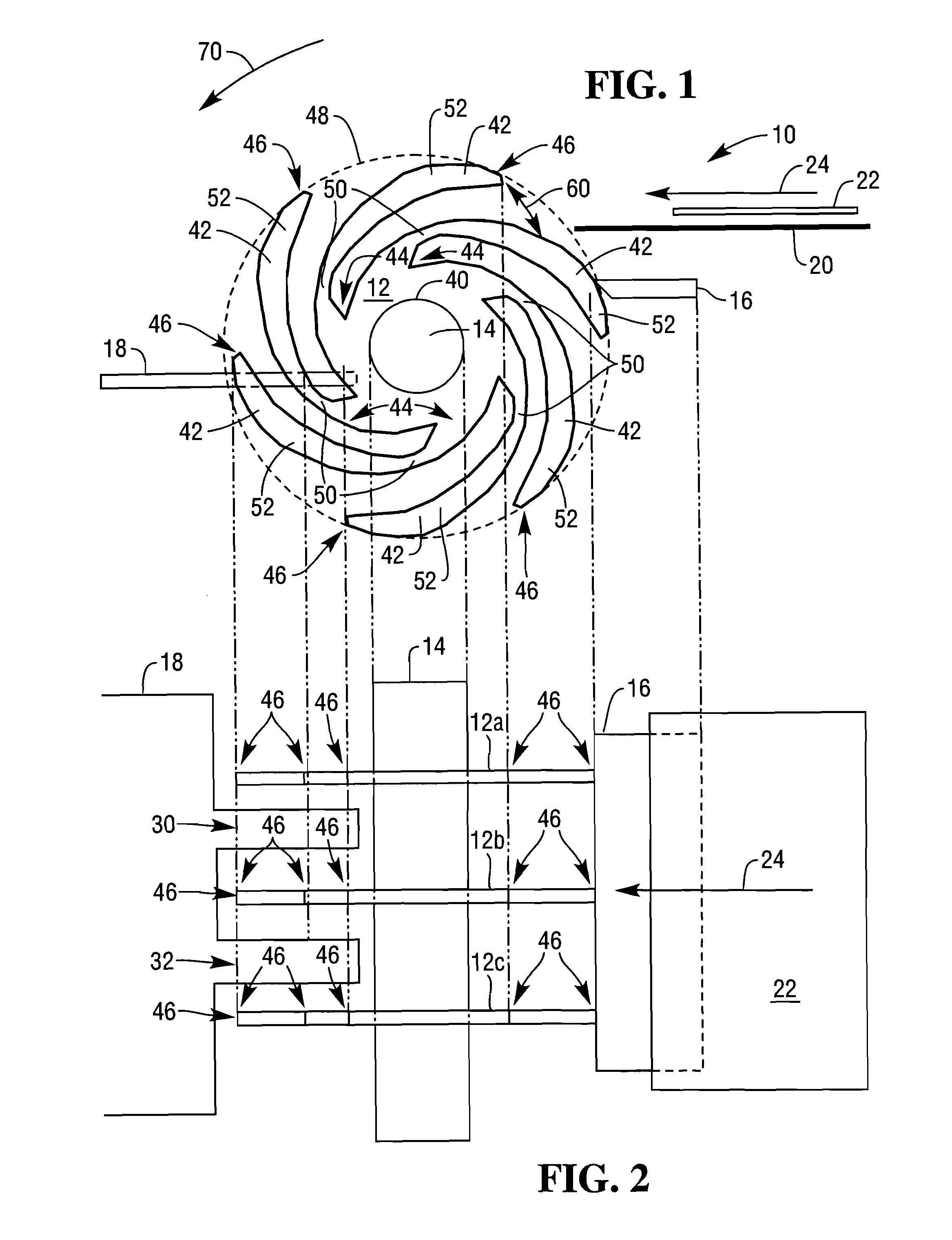
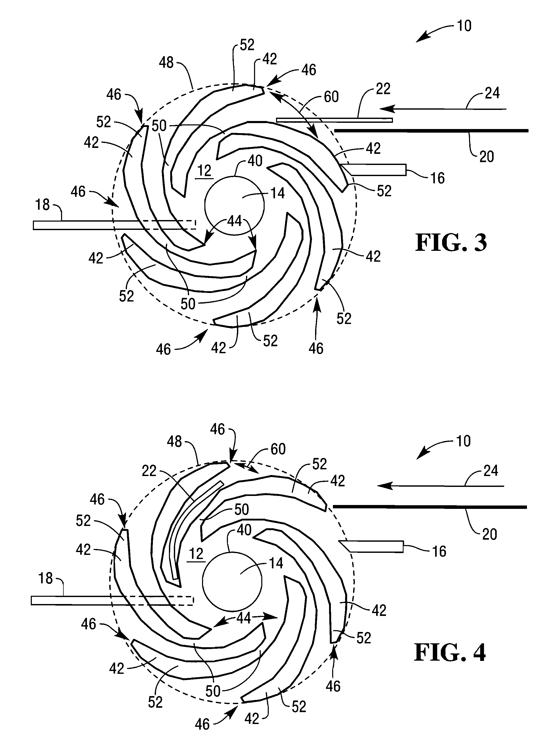
[0031]Reference is first made to FIGS. 1 and 2, which are side and plan views respectively of a stacker unit 10 according to one embodiment of the present invention.

[0032]The stacker unit 10 comprises a stacker wheel 12 mounted on an axle 14 and having a detent 16 on a media item input side of the stacker unit 10. A conventional collecting plate 18 is mounted adjacent the stacker unit 10 on a collation side of the stacker unit 10.

[0033]The media item input side includes a media transport 20 for transporting media items 22 (in this embodiment, banknotes) to the stacker unit 10 in the direction shown by arrow 24.

[0034]The collecting plate 18 includes a pair of arms 30,32 extending between adjacent stacker wheels 12a,b, and 12b,c and operates in a conventional manner.

[0035]The stacker wheel 12 is made of polyamide and comprises a central hub 40 mounted on the axle 14, and a plurality of arcuate tines 42 (in this embodiment, six tines are shown). Each tine 42 is coupled to the hub 40 at...


PUM

PropertyMeasurementUnit
timeaaaaaaaaaa
lengthaaaaaaaaaa
metallicaaaaaaaaaa

Abstract

A media stacker unit comprises: (i) at least one stacker wheel and (ii) a detent. The stacker wheel includes: a hub for mounting on an axle, and a plurality of arcuate tines, each tine being coupled to the hub at a hub end and extending transverse to the axle to a point radially spaced from the axle at a capture end. When the stacker wheel is rotated about the axle, the capture ends traverse a capture circumference. Each tine further comprises a resilient tine portion. The detent partially extends within the capture circumference for engaging with and temporarily retarding a capture end as the stacker wheel is rotated. This reduces the time during which that capture end blocks a media transport path, thereby reducing the possibility of a media item colliding with a capture end and jamming the media stacker unit.

Description

FIELD OF INVENTION[0001]The present invention relates to an improved media stacker.BACKGROUND INVENTION[0002]Media stackers typically include wheels that are used to collate media items, such as banknotes, to enable those collated media items to be conveyed as a bunch.[0003]A stacker wheel typically comprises an axially-mounted hub, and a plurality of arcuate tines extending transverse to the axle on which the hub is mounted.[0004]A stacker unit comprises a plurality of mutually coupled but axially separated stacker wheels. The stacker wheels are rotated in unison as media items are fed into the stacker wheels from one side (the media item input side). The speed at which the media items are conveyed is synchronized with the rotation of the stacker wheels so that only one media item is stored between adjacent tines.[0005]A pivoting collecting plate is typically located at the opposite side of the stacker unit to the media item input side. The collecting plate comprises a plurality of...

Claims


Application Information

Patent Timeline
Patent Type & Authority Patents(United States)
IPC IPC(8): B65H29/20
CPCB65H29/40B65H2701/1912B65H2404/657B65H2301/42146
Inventor WYLIE, CHRISTOPHER W.
Owner NCR CORP
Why Eureka
Try Eureka