LED luminaire
a technology of led luminaires and diodes, which is applied in the direction of lighting and heating apparatus, process and machine control, instruments, etc., can solve the problems of difficult to adjust the chromaticity based on the light of the mixed-color obtained from these leds, and the difficulty in detecting light stably from all leds, so as to reduce the disturbance caused by ambient light, increase the design flexibility of led luminaires, and efficient transmittance
- Summary
- Abstract
- Description
- Claims
- Application Information
AI Technical Summary
Benefits of technology
Problems solved by technology
Method used
Image
Examples
first embodiment
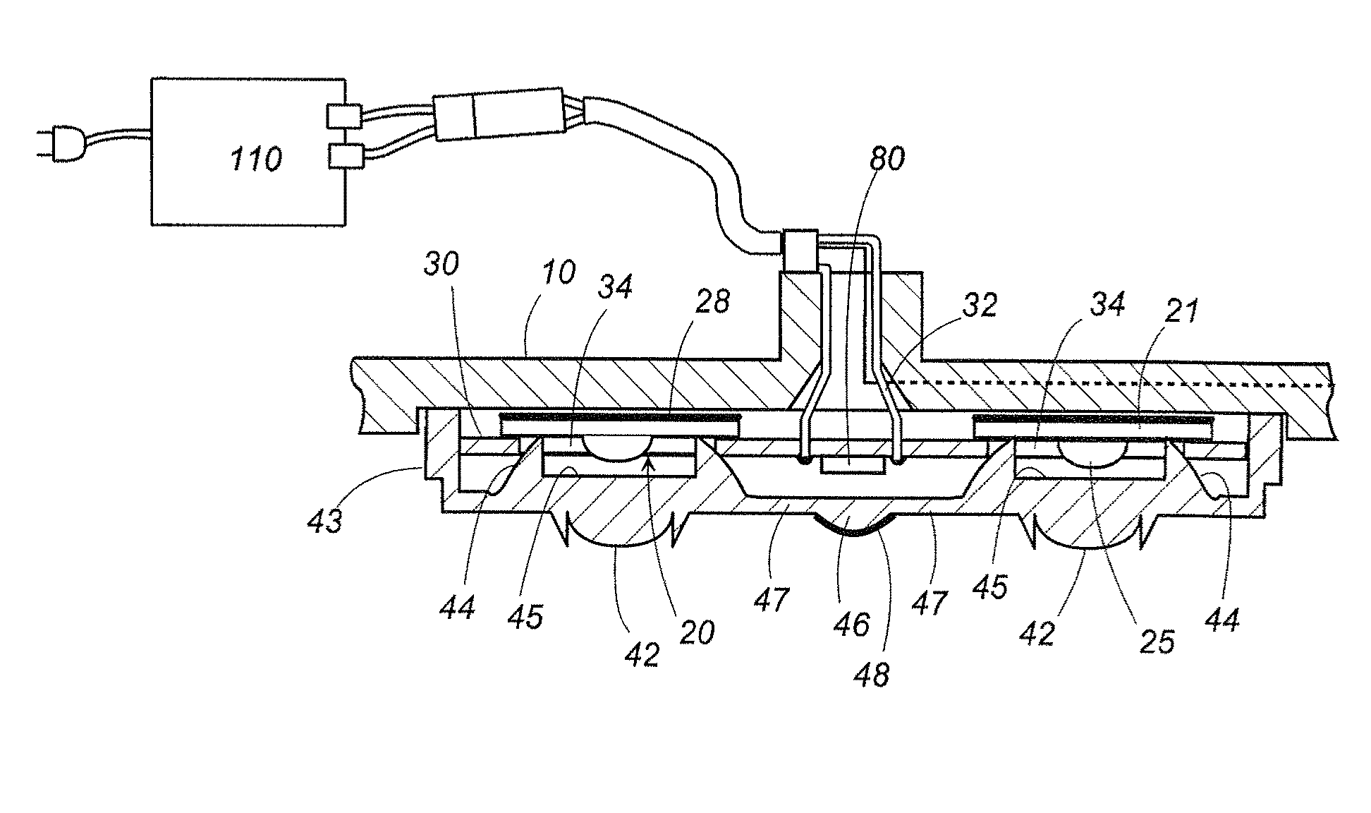
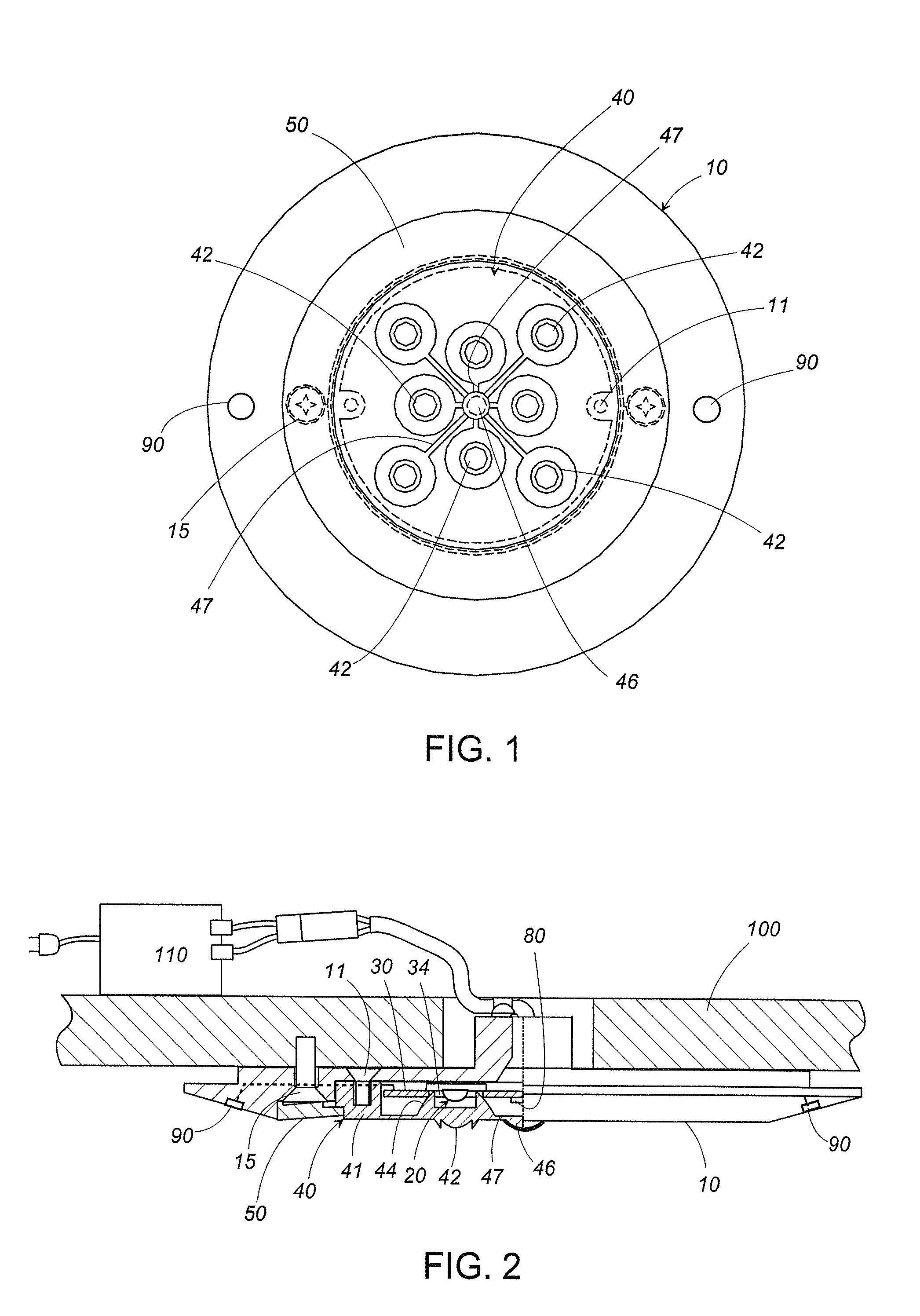
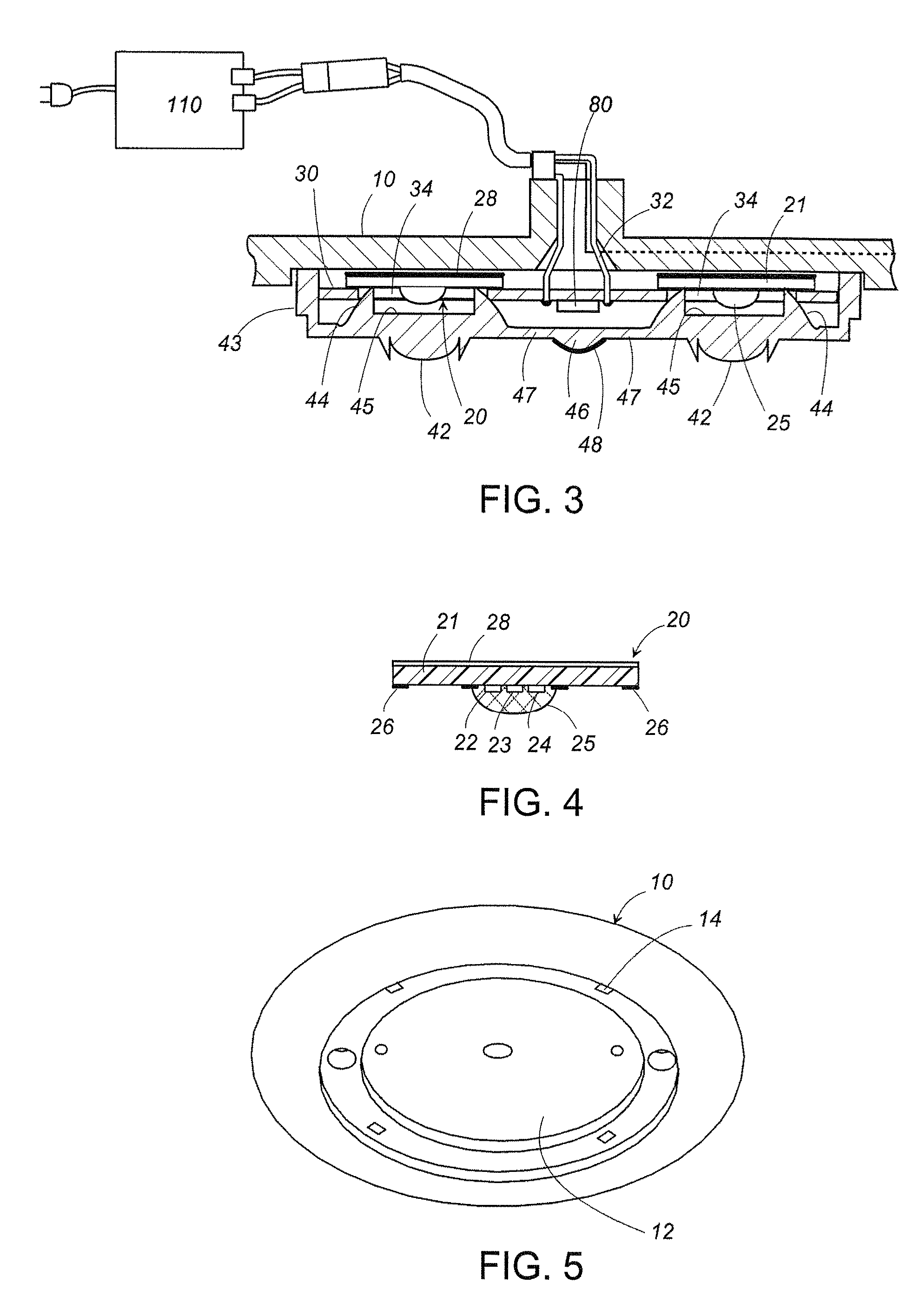
[0033]The LED luminaire in accordance with the present invention will be described with reference to FIGS. 1 to 10. The LED luminaire in accordance with this embodiment is configured as a ceiling light. As shown in FIG. 2, the LED luminaire includes a disc-shaped main body 10 attached to a ceiling 100, a plurality of light emitting modules 20 arranged on a front surface of the main body 10, and a lens unit 40 covering a plurality of the light emitting modules 20 on the front surface of the main body 10. As shown in FIG. 5, a circular recess 12 is formed on the front surface of the main body 10 to accommodate a plurality of the light emitting modules 20 and the lens unit 40. Furthermore, a decorative ring 50 is attached to a periphery of the recess 12 of the main body 10 to surround the lens unit 40, while concealing screws 15 used for securing the main body 10 to the ceiling 100. As shown in FIG. 8, the decorative ring 50 is removably attached to the main body 10 with hooks 52 proje...
second embodiment
[0051]FIG. 18 shows a first modification of the In this modification, the control unit 70 is provided separately from the main body 10, and accommodates therein the light sensor 80 together with the light output controller 60, and the light guide 47 extending from the center of the back surface of the lens unit 40 is optically coupled to the light sensor 80 through an optical fiber 72. The tip of the light guide 47 is inserted into the thermal insulation sleeve 18 which is embedded within the tube 16 projecting to the back surface of the main body 10. Here, the tip is connected to one end of the optical fiber 72. The other end of the optical fiber 72 is coupled to the light sensor 80 in the control unit 70. The modification also includes a hollow cavity 45 at the center of the lens unit 40. A film of the reflector 48 is provided on the wall of hollow cavity 45, preventing the light from traveling to the light guide 47 extending from the back surface opposite to the hollow cavity 45...
PUM
 Abstract
Description
Claims
Application Information
 - R&D
- Intellectual Property
- Life Sciences
- Materials
- Tech Scout
- Unparalleled Data Quality
- Higher Quality Content
- 60% Fewer Hallucinations
Browse by: Latest US Patents, China's latest patents, Technical Efficacy Thesaurus, Application Domain, Technology Topic, Popular Technical Reports.
© 2025 PatSnap. All rights reserved.Legal|Privacy policy|Modern Slavery Act Transparency Statement|Sitemap|About US| Contact US: help@patsnap.com


