LED luminaire

Active Publication Date: 2010-09-02
MATSUSHITA ELECTRIC WORKS LTD
View PDF6 Cites 25 Cited by
  • Summary
  • Abstract
  • Description
  • Claims
  • Application Information

AI Technical Summary

Benefits of technology

[0011]Moreover, the light sensor may be incorporated into a control unit provided separately from the main body. In this case, the light guide extends to the back surface of the main body through the circuit board, and is coupled to the light sensor by means of an optical fiber. With the above configuration, the mixed-color light from the light emitting module can be efficiently transmitted to the control unit provided separately from the main body, for increasing design flexibility of the LED luminaire.
[0012]Furthermore, the lens unit is preferably provided with a reflector. The reflector reflects the external light entering from a front side of the lens unit, such that the light from the light emitting module is directed from the light guide into a path leading to the light sensor for reducing disturbances caused by an ambient light. Consequently, the light sensor can detect the mixed-color light only from the light emitting module for accurate adjustment of chromaticity.
[0013]The reflector may be formed on one side of faces of a hollow cavity formed in the lens unit. With the reflector thus formed

Problems solved by technology

However, since the emitted light from each of LEDs is transmitted to the photodiode through an optical fiber, the LED luminaire has one disadvantage that it is difficult to detect light stably from all of the LEDs.
Furthermore, since the control unit drives the red, green, and blue LEDs indivi

Method used


Image

  • LED luminaire
  • LED luminaire
  • LED luminaire

Examples


first embodiment

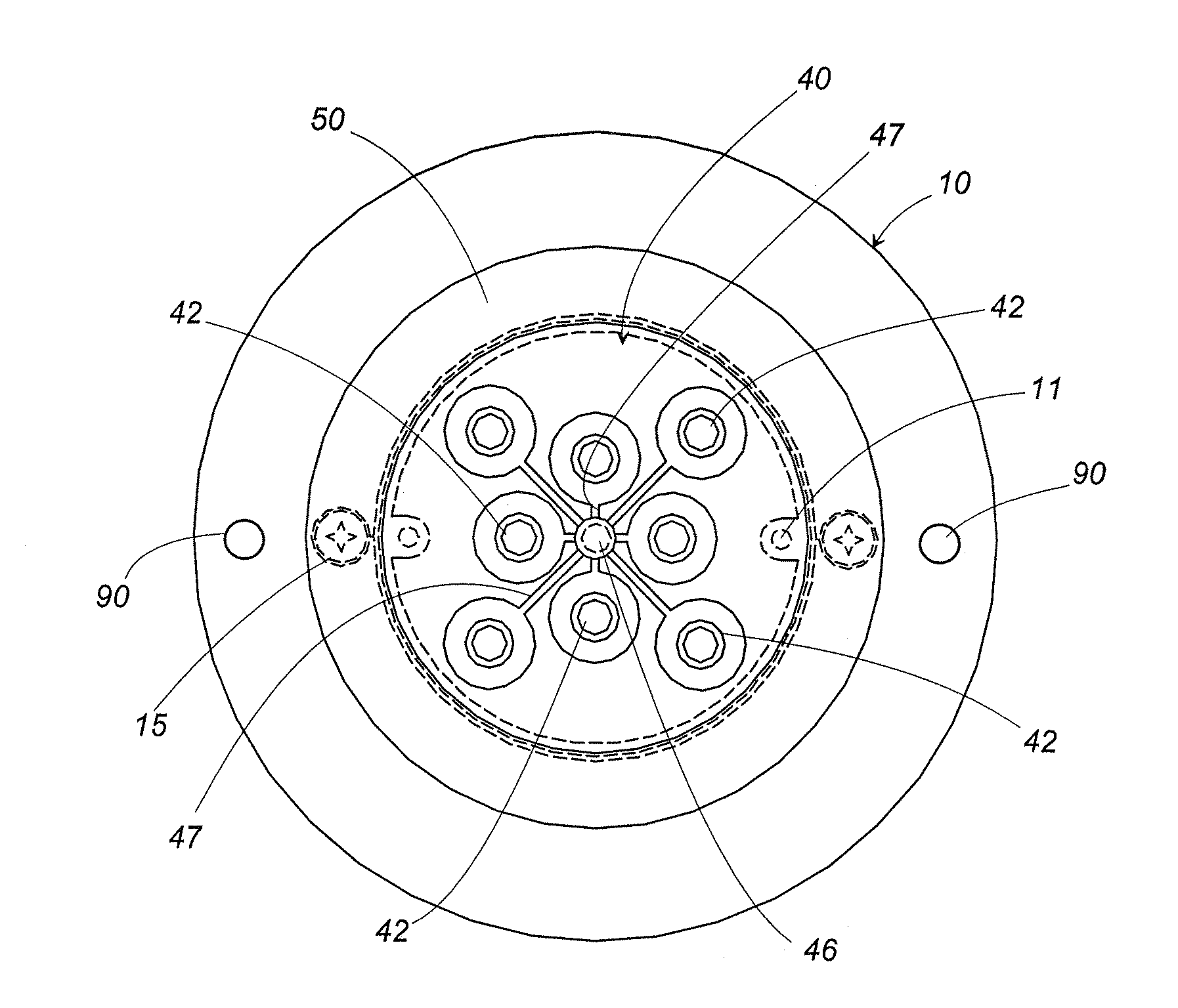
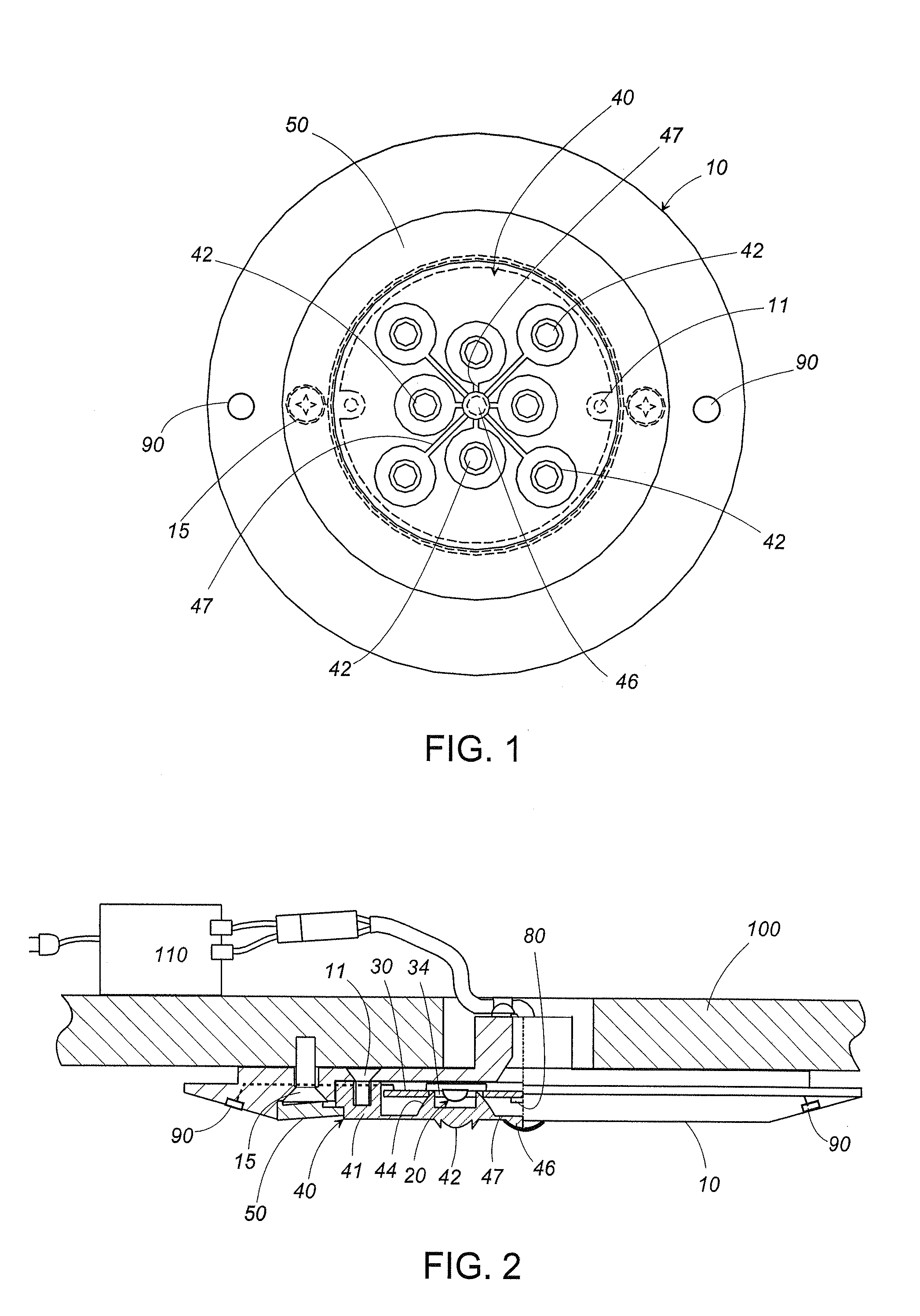
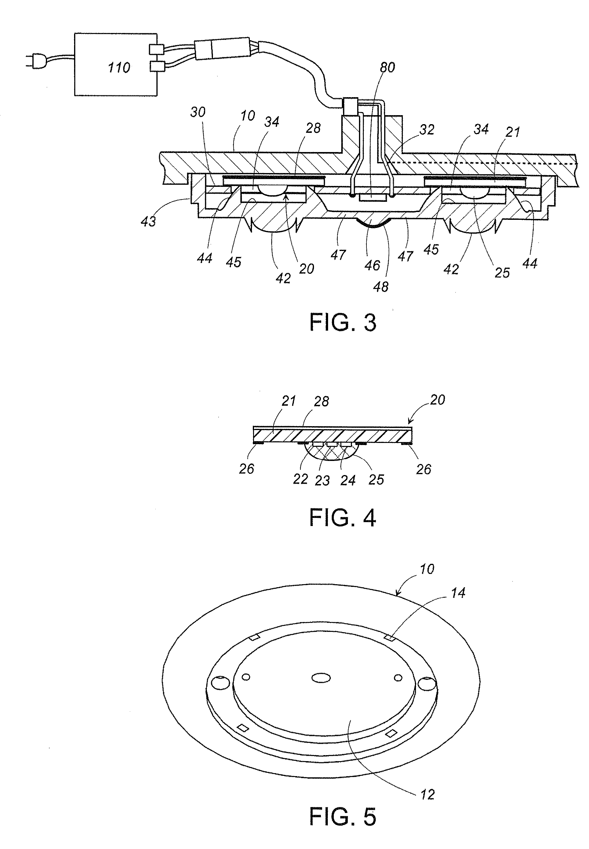
[0033]The LED luminaire in accordance with the present invention will be described with reference to FIGS. 1 to 10. The LED luminaire in accordance with this embodiment is configured as a ceiling light. As shown in FIG. 2, the LED luminaire includes a disc-shaped main body 10 attached to a ceiling 100, a plurality of light emitting modules 20 arranged on a front surface of the main body 10, and a lens unit 40 covering a plurality of the light emitting modules 20 on the front surface of the main body 10. As shown in FIG. 5, a circular recess 12 is formed on the front surface of the main body 10 to accommodate a plurality of the light emitting modules 20 and the lens unit 40. Furthermore, a decorative ring 50 is attached to a periphery of the recess 12 of the main body 10 to surround the lens unit 40, while concealing screws 15 used for securing the main body 10 to the ceiling 100. As shown in FIG. 8, the decorative ring 50 is removably attached to the main body 10 with hooks 52 proje...

second embodiment

[0051]FIG. 18 shows a first modification of the In this modification, the control unit 70 is provided separately from the main body 10, and accommodates therein the light sensor 80 together with the light output controller 60, and the light guide 47 extending from the center of the back surface of the lens unit 40 is optically coupled to the light sensor 80 through an optical fiber 72. The tip of the light guide 47 is inserted into the thermal insulation sleeve 18 which is embedded within the tube 16 projecting to the back surface of the main body 10. Here, the tip is connected to one end of the optical fiber 72. The other end of the optical fiber 72 is coupled to the light sensor 80 in the control unit 70. The modification also includes a hollow cavity 45 at the center of the lens unit 40. A film of the reflector 48 is provided on the wall of hollow cavity 45, preventing the light from traveling to the light guide 47 extending from the back surface opposite to the hollow cavity 45...


PUM


Abstract

An LED luminaire is provided with a light emitting module composed of plural kinds of LEDs emitting lights of different colors, a lens unit having a lens for diffusing the mixed-color light from the light emitting module, a light output controller for controlling electric current fed to each of the LEDs, and a light sensor for sensing the light from the light emitting module. The light output controller performs feedback control on the electric current fed to each of the LEDs based upon light levels of the sensed light, so that the light emitted from the light emitting module has desired chromaticity. The lens unit contains a light guide for guiding the light from the lens to the light sensor and can guide the light from the light emitting module to the light sensor with a high efficiency.

Description

TECHNICAL FIELD[0001]The present invention relates to a light emitting diode luminaire composed of LEDs of different colors to emit a light of desired chromaticity.BACKGROUND ART[0002]International Patent Publication No. WO0037904 discloses a conventional LED luminaire. The LED luminaire includes a circuit board mounting thereon plural kinds of LEDs of different colors (e.g., a red LED, a green LED, and a blue LED), a main body carrying the circuit board, and an optical member covering surfaces of the LEDs. In order to obtain a light of a desired chromaticity (e.g., white light), the LED luminaire further includes a single photodiode for detecting light outputs from all of the LEDs and a controller for performing a feedback control of regulating an amount of forward electric current to each LED in order to keep the light from the individual LED at a predetermined desired level. However, since the emitted light from each of LEDs is transmitted to the photodiode through an optical fib...

Claims


Application Information

Patent Timeline
IPC IPC(8): H05B37/02H05B44/00
CPCF21V5/04F21Y2101/02H05B33/0827Y10S362/803F21V23/0457Y10S362/80H05B33/0869F21Y2115/10H05B45/22H05B45/46F21V5/007
Inventor TANAKA, KENICHIROIWAHORI, YUTAKASUZUKI, YUJI
Owner MATSUSHITA ELECTRIC WORKS LTD
Why Eureka
Try Eureka