
Cooling channel formed in a wall

a cooling channel and wall technology, applied in the direction of machine/engine, manufacturing tools, solventing apparatus, etc., can solve the problems of long and expensive operation, particularly complex shape of the electrode, and the inability to form a channel by electroerosion using known methods, and achieve the effect of reducing costs

Active Publication Date: 2011-05-31
SAFRAN AIRCRAFT ENGINES SAS
View PDF32 Cites 9 Cited by
  • Summary
  • Abstract
  • Description
  • Claims
  • Application Information

AI Technical Summary

Benefits of technology

This approach significantly reduces the time and cost of forming cooling channels while preventing crack formation and ensuring effective air guidance and spreading for efficient cooling of the outside surface.

Problems solved by technology

As can be seen, the shape of that electrode is particularly complex.
In addition, in general manner, forming a channel by electroerosion using known methods remains an operation that is lengthy and expensive.

Method used


Image

  • Cooling channel formed in a wall
  • Cooling channel formed in a wall
  • Cooling channel formed in a wall

Examples


Embodiment Construction

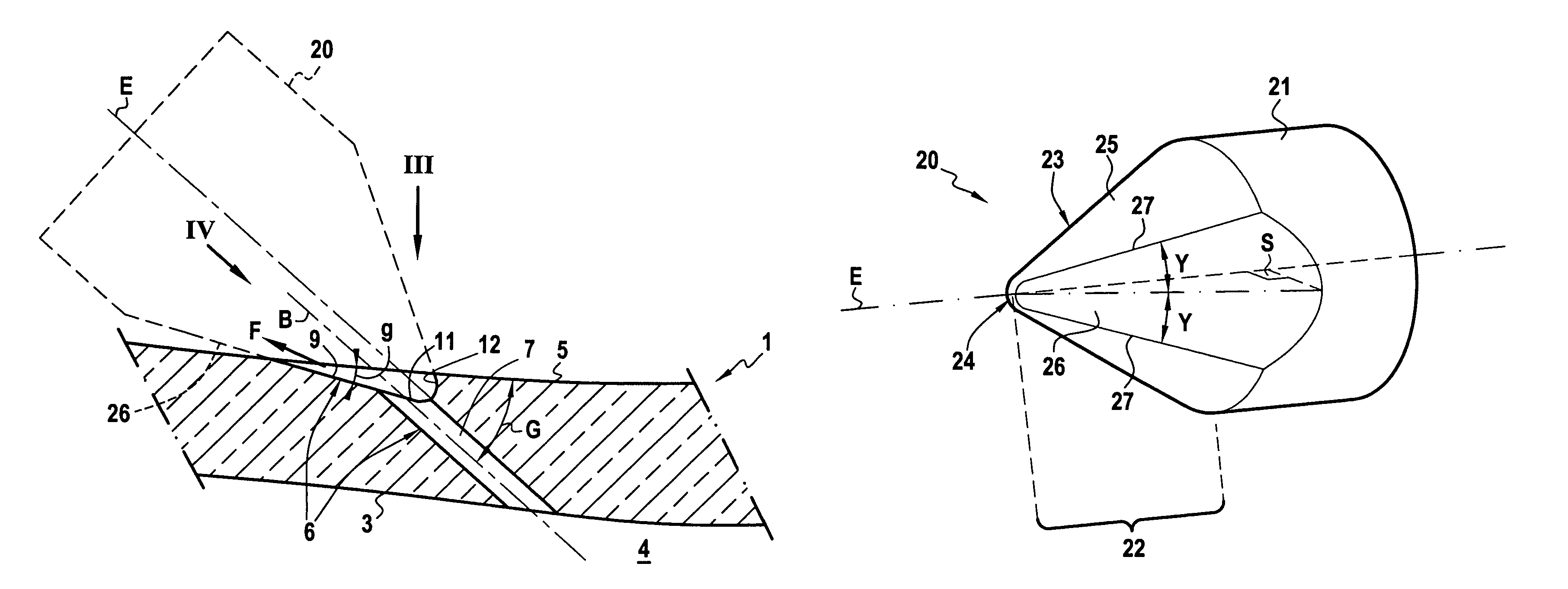
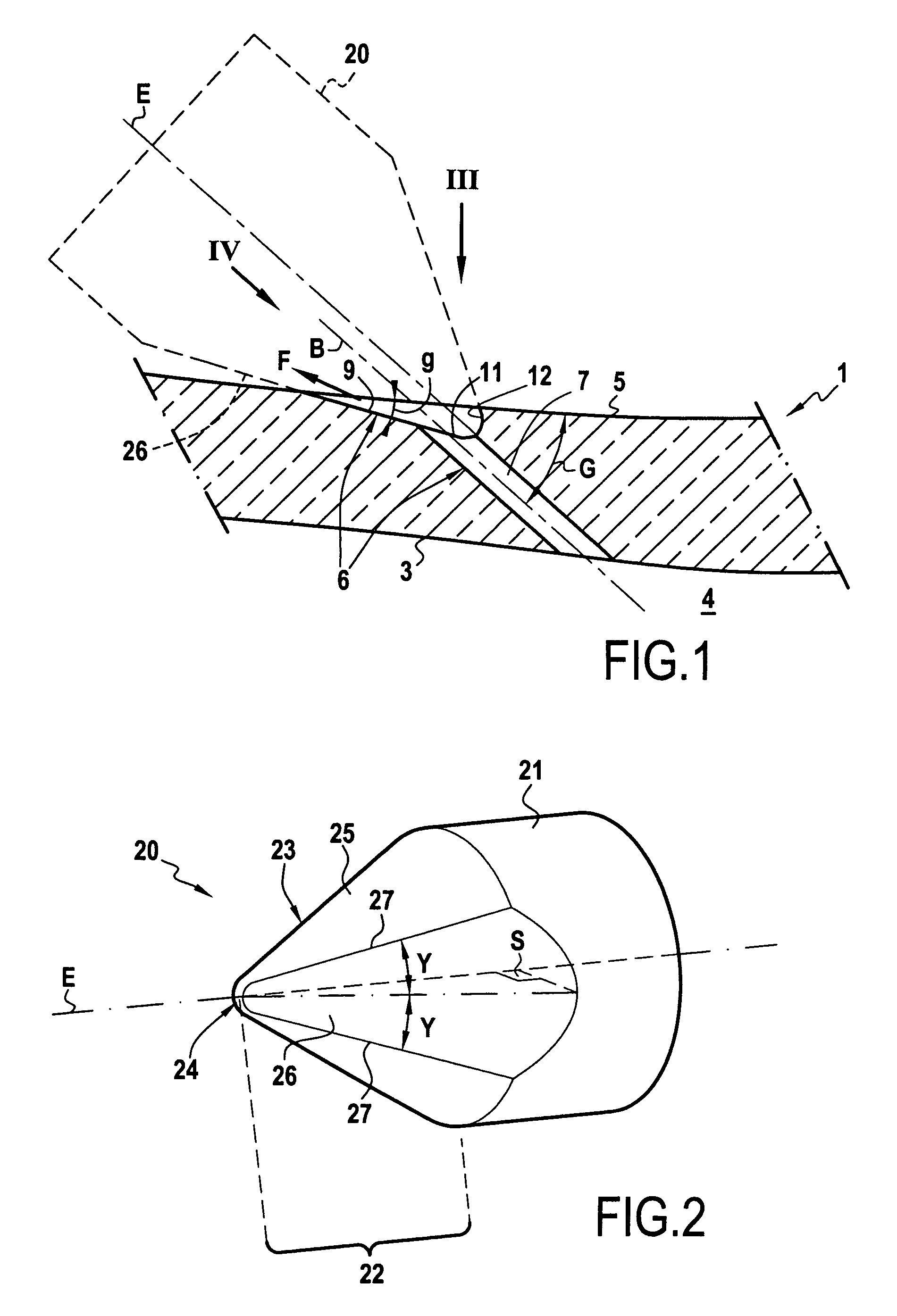
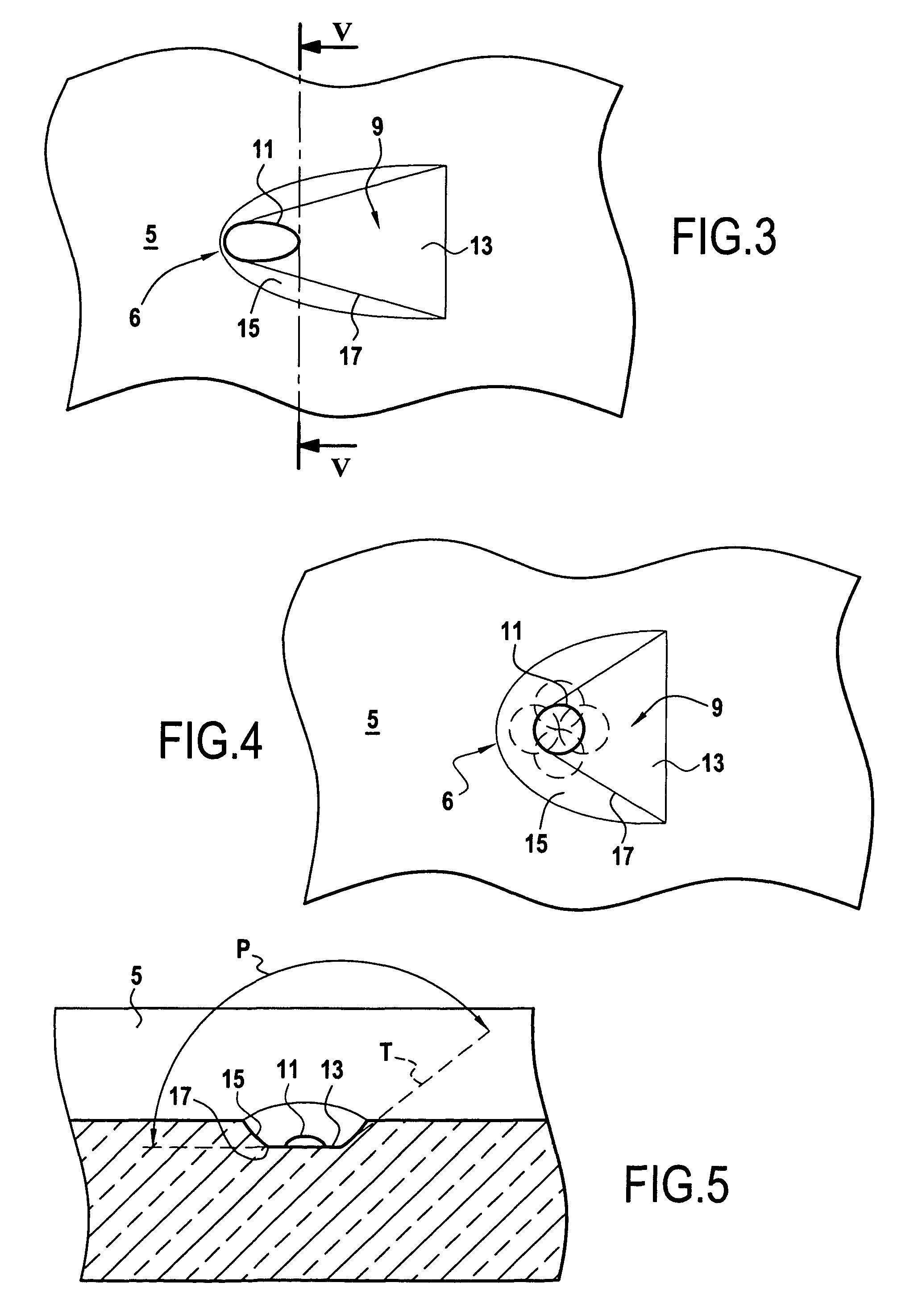
[0024]With reference to FIGS. 1, 3, 4, and 5, there follows a description of an example of a wall element of the invention.

[0025]Said wall element presents an inside surface 3 and an outside surface 5. This element belongs to a wall 1 of a hollow gas-turbine blade, such as a high pressure turbine blade of a turbojet. This type of hollow blade has an internal cooling passage 4 defined in part by the inside surface 3, said passage being fed with cool air.

[0026]The outside surface 5 of the wall is subjected to the hot gas passing through the turbine and it therefore needs to be cooled. For this purpose, cooling channels are provided in the wall 1. At least some of these channels are of the same type as the channel shown in FIG. 1. This channel 6 passes cool air coming from the internal cooling passage 4 of the blade and delivers this cool air to the outside surface 5 in order to cool it. The channel 6 comprises two portions: an adjustment portion formed by a hole 7, and a diffusion por...


PUM


Abstract

A wall in which there is formed at least one cooling channel, said wall being cooled by cool air flowing in the channel, the channel comprising a hole and a diffusion portion, the hole opening out at one end into the inside surface of the wall, and at its other end into the diffusion portion where it forms an orifice, the diffusion portion flaring around said orifice and opening out into the outside surface of the wall, the diffusion portion having a bottom whose front end is substantially plane, sloping, and extending in front of the orifice, and also having a margin extending behind, round the sides, and in front of the orifice, said margin joining the sides of the front end. A method and an electrode for making such a cooling channel. A turbomachine blade presenting such a wall.

Description

[0001]The invention relates to a method of forming a cooling channel in a wall, to an electrode used for implementing the method, to a wall element in which a cooling channel is formed, and to a hollow turbomachine blade including a wall element of this type.FIELD OF THE INVENTION[0002]More precisely, the invention relates to a wall element of the type comprising an inside surface and an outside surface, the outside surface being suitable for being cooled by cool air flowing in said cooling channel. In addition, the cooling channel is of the type comprising a hole and a diffusion portion, the hole opening out at one end into the inside surface of the wall and at its other end substantially into the bottom of the diffusion portion by forming an orifice, and the diffusion portion flaring away from said orifice and opening out into the outside surface of the wall.BACKGROUND OF THE INVENTION[0003]U.S. Pat. No. 6,183,199 B1 shows an example of a wall element for a hollow blade of a turbo...

Claims


Application Information

Patent Timeline
Patent Type & Authority Patents(United States)
IPC IPC(8): F01D5/18
CPCF01D5/186B23H9/10B23H1/04F05D2250/232Y10T29/49341F05D2230/13Y10T29/49336F05D2230/12B23K35/0216
Inventor CAMHI, EMMANUEL PIERRECROUILBOIS, LAURENTMAREIX, JEAN PIERREPASQUIET, DIDIER
Owner SAFRAN AIRCRAFT ENGINES SAS
Learn More